um..i need more help than i want
since i didn't use those bias resistor anymore (i'm using a 1k multi-turn trimpot instead, and nothing connected to ground), how i should connect the DC servo?
thanks!")
Disconnect ground end of R8 from ground. Connect output of integrator (Vout) to this end of R8. If you have feedback capacitor still in series with R8 make sure it goes from end of R8/Servo output to ground i.e. it can be left in.
Go careful! I have NOT tried this apart from a few years ago on a headphone amp circuit! Use a cheapo speaker for initial testing after determining the circuit is indeed giving improved offset performance!!
Last edited:
Audio Mosfets. have negative temperature coefficient, they tend to draw reduced current the more they heat up. RDS is relatively high too, you can parallel them without current sharing resistors no problem. They'll settle at whatever bias you set within reason. Look at the classic Hitachi mosfet app circuit it too only uses a variable resistor for bias setting, temp compensation not normally required.
But he's not using audio MOSFETs, they are vertical type. You cannot parallel them without source resistors.
Blu_glo is right. I should have looked more closely at the datasheet. The tempco is very moderate for the N-channel side (attached) and even better for the P-channel mosfet. It should be fine. I had assumed these were switching transistors which don't fare as well.
They are switching MOSFETS, but not as sensitive to temperature as BJT. They are actually great devices for audio, better than IR. Unfortunately discontinued a while ago now.
Disconnect ground end of R8 from ground. Connect output of integrator (Vout) to this end of R8. If you have feedback capacitor still in series with R8 make sure it goes from end of R8/Servo output to ground i.e. it can be left in.
Go careful! I have NOT tried this apart from a few years ago on a headphone amp circuit! Use a cheapo speaker for initial testing after determining the circuit is indeed giving improved offset performance!!
i don't have them installed right now.somehow 1 module accept it and the other don't want it
okay.VOut goes to the R8 end, the + input goes to the ground, and what about the - input other than small C like 0.22 or more to the output?
and why test w/ speakers?..can i just test them w/ DMM instead?
But he's not using audio MOSFETs, they are vertical type. You cannot parallel them without source resistors.
They are switching MOSFETS, but not as sensitive to temperature as BJT. They are actually great devices for audio, better than IR. Unfortunately discontinued a while ago now.
no more vertical 2SJ/SK mosfets?..now i regret to blow a pair of them
the lateral was pretty expensive for me
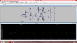
somehow i got this idea originally (being playing around w/ LTS since this evening )
is it practical?.please note that i put back the feedback caps on this circuit (don't know if i would use them or not since i already added input caps on the modules).
and the offset isn't rock stable even they didn't go crazy.is it good?
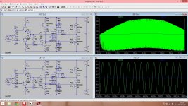
just in case you couldn't see the schematic, the output of LT1007 goes to 1MOhm and the end of it goes to the feedback (after the 5.6kOhm feedback resistor).the + input goes to ground, and the - input goes to the amp output w/ 1kOhm resistor
zener on the opamp output just for protection in case something goes wrong later (not now, but maybe a month/year/decade later )
)is it practical?.please note that i put back the feedback caps on this circuit (don't know if i would use them or not since i already added input caps on the modules).
and the offset isn't rock stable even they didn't go crazy.is it good?
just in case you couldn't see the schematic, the output of LT1007 goes to 1MOhm and the end of it goes to the feedback (after the 5.6kOhm feedback resistor).the + input goes to ground, and the - input goes to the amp output w/ 1kOhm resistor
zener on the opamp output just for protection in case something goes wrong later (not now, but maybe a month/year/decade later
)Attachments
Last edited:
I gave you the link to the opamp circuit top of post #7 and the explanation in the message after.
I can do a diagram but not right now.... and 1K input resistor is not enough it'll need to be much more, as suggested.
okay.i'll try a bigger R value.4.7kOhm enough?.or 1MOhm?
aah...i tried to put the VOut after the feedback caps and it works pretty well!.
.but i couldn't link it to R11 since i didn't use them anymore.i guess the only way is linking it to R8 after the caps?
Last edited:
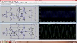
err...i got problem here..i tried to simulate it again this morning but ended the circuit didn't work
if i put the VOut after the feedback caps, no additional resistance means broken signal and with additional signal, it's way too low.
but if i put the VOut just after the feedback resistor, it works with additional resistor
did i missed something there?
feeling so dumb
if i put the VOut after the feedback caps, no additional resistance means broken signal and with additional signal, it's way too low.
but if i put the VOut just after the feedback resistor, it works with additional resistor
did i missed something there?
feeling so dumb
Attachments
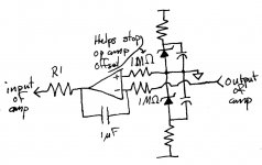
The op amp cannot control DC through a capacitor. It will raise or lower the voltage of the capacitor, then the capacitor will fill up and act like a short circuit. That is why the resistor has to be attached there. Then you don't need the capacitor at all, because the op-amp does its job. However, there is another issue.
The op amp needs to be configured as an "integrator" or low-pass filter to work as a servo. Otherwise, it ties to control the whole signal in the amp. The simplest kind are inverting, like the attached picture. This would be connected to the input of the amp, but you must have an input cap.
If you want to use the connection points you have, you need a non-inverting integrator.
Attachments
Your circuit may be experiencing a very low frequency oscillation. Have you tried including low value (maybe, 1 ohm or less) source degeneration resistors on the MOSFETS? They could improve loop stability.
i don't really know since i don't have oscilloscope here.but who knows?.it might be
.so, thanks for the advice!.i'll try to increase it up.1Ohm seems the safest?Audio Mosfets. have negative temperature coefficient, they tend to draw reduced current the more they heat up. RDS is relatively high too, you can parallel them without current sharing resistors no problem. They'll settle at whatever bias you set within reason. Look at the classic Hitachi mosfet app circuit it too only uses a variable resistor for bias setting, temp compensation not normally required.
Vertical mosFETs like the irf240 are not thermally stable.Blu_glo is right. I should have looked more closely at the datasheet. The tempco is very moderate for the N-channel side (attached) and even better for the P-channel mosfet. It should be fine. I had assumed these were switching transistors which don't fare as well.
They are positive coefficient at all quiescent currents.
The change to thermally stable, negative coefficient, occurs at currents that are generally very short term,. i.e. transient currents to the reactive load.
Lateral mosFETs that change from +ve to -ve coefficient at around 100mA can be used without a tempco compensator if the circuit is designed for such thermal stability
Last edited by a moderator:
Vertical mosFETs like the irf240 are not thermally stable.
They are positive coefficient at all quiescent currents.
The change to thermally stable, negative coefficient, occurs at currents that are generally very short term,. i.e. transient currents to the reactive load.
Lateral mosFETs that change from -ve to -ve coefficient at around 100mA can be used without a tempco compensator if the circuit is designed for such thermal stability
http://www.irf.com/product-info/datasheets/data/irf240.pdf
Have to admit now
P.3 figures 3 and 4 seem to offer contradicting graphs... while the datasheet early on boasts of "ease of paralleling" in the long term I'd say better to stick with *proper* audio mosfets....The ease of paralleling refers to their intended application of switching, where the high current bursts fit in the profile of the tempco transistion point.
Indeed and the somewhat dubious third paragraph p.1 does indeed say Switching ... ... ... audio amplifiers so the OP circuit is not really using them in quite the right way.
I have to say my experience ends here as I used the old hitachi lateral FETs 2SJ82 and its partner -K266 plus I have worked on the old Maplin "150W" modules with the TO3 types.
- Status
- This old topic is closed. If you want to reopen this topic, contact a moderator using the "Report Post" button.
- Home
- Amplifiers
- Solid State
- unstable DC offset