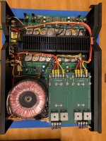
Hi Chamberman
Thank you for the compliment and yes, you are right, I have not included the pre-drivers but they are next on the list. The output module has been languishing in the corner of the workshop for so long I thought it would be good to show at least some progress on it!
Hopefully, I'll get the pre-drivers soon and will then send a couple of pics.
Al the best
donf
Aragon 2004
Hi All -
So after a few years in storage - I am trying to get my 2004 up and running again. I have that low hum in the speakers and am pretty sure it is the capacitors. I have them pulled out. Can anyone tell me the best capacitors to replace the old ones with and where to find them. This seems a bit tough to find the right part.
Cheers
Tim
Hi folks.
It is now 2020, five years on, and I can finally say that the Aragon 2004 is up and running. Events got in the way, moving around, day job, etc etc. So the project had to go on hold for a while until I had established a decent workshop rather than a table top in an apartment.
For completeness, I'll post the last stages of the restoration.
Firstly, as suggested by Chamberman, I replaced Q1/Q2/Q7/Q8 with the MJE15030/MJE15031 combination.
I completed the amplifier module that featured here and also replaced the bias transistor Q13 since I had a couple of these spare.
Following exactly the same procedure as described before, I replaced transistors in the second amplifier module using the same thermal grease.
I now had both boards ready for installation in the amplifier chassis.
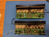
Fig 12 Aragon 4004 Mk2 – restored amplifier modules
The next thing to do was replace two weakened fuse clips on the power supply board and the two 10 Ohm resistors in the small separate ground board. I then cleaned the inside of the amplifier of any residual dust and prepared to connect the amplifier modules. While the identification of the cables was reasonably easy I had a good number of photos of the amplifier to assist me with reconnection.
I reinstalled both boards and connected the cables.
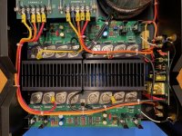
Fig 13 Aragon 4004 Mk2 – amplifier modules re-installed
I then needed to adjust the bias and offset of each channel. I followed the procedure discussed in an old thread I discovered on the Klipsch forum which I will describe in a following post.
It is now 2020, five years on, and I can finally say that the Aragon 2004 is up and running. Events got in the way, moving around, day job, etc etc. So the project had to go on hold for a while until I had established a decent workshop rather than a table top in an apartment.
For completeness, I'll post the last stages of the restoration.
Firstly, as suggested by Chamberman, I replaced Q1/Q2/Q7/Q8 with the MJE15030/MJE15031 combination.
I completed the amplifier module that featured here and also replaced the bias transistor Q13 since I had a couple of these spare.
Following exactly the same procedure as described before, I replaced transistors in the second amplifier module using the same thermal grease.
I now had both boards ready for installation in the amplifier chassis.

Fig 12 Aragon 4004 Mk2 – restored amplifier modules
The next thing to do was replace two weakened fuse clips on the power supply board and the two 10 Ohm resistors in the small separate ground board. I then cleaned the inside of the amplifier of any residual dust and prepared to connect the amplifier modules. While the identification of the cables was reasonably easy I had a good number of photos of the amplifier to assist me with reconnection.
I reinstalled both boards and connected the cables.

Fig 13 Aragon 4004 Mk2 – amplifier modules re-installed
I then needed to adjust the bias and offset of each channel. I followed the procedure discussed in an old thread I discovered on the Klipsch forum which I will describe in a following post.
Setting the Aragon 2005 bias and offset
Having completed the amplifier internal connections I ran the amplifier up on a Variac to make sure that the power supply was starting well and that everything was OK. No problems there.
As I mentioned in the earlier post I discovered a conversation on the Klipsch forums between Steve Donaldson, a Jamo technical support specialist and another guy Oliver. That conversation gave me all I needed.
Steve sets out the procedure:
Here's how you would check/adjust the bias and DC offset:
1. Place a voltmeter across any of the emitter resistors. Adjust bias adjustment pot. for a reading of 10mV +/- 2mV. Repeat for the other channel.
2. Short the input, place a voltmeter across the output of the shorted channel. Adjust DC offset pot for a reading of 0.00VDC +/- .01V. Repeat for other channel.
3. Allow amp to burn in for a minimum of 4 hours. Then remove signal and allow to idle for 20 minutes. Repeat steps 1 and 2.
Here is a photo of the amplifier module they are talking about with the bias and DC offset pots identified.
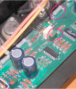
Fig 14 Aragon 4004 bias and DC offset adjustment
In his reply, Oliver says:
"So I put the voltmeter to the legs of the emitter resistors and after some adjusting measured something around the high 7s to the low 12 in voltage.
There is quite some variation in between the resistors and it seems the middle value is pretty close to 10mV, that Ok ?
Now I would have to adjust DC offset, that is the blue encircled pot ?"
To which Steve replies:
"That should be fine and yes, the one circled in blue is the DC offset pot."
My experience was the same as Oliver's in that the offset readings across the emitter resistors varied between roughly 9.0mV and 12mV. The DC offset went well and I obtained 0.00 Volt on both channels.
I removed the Variac and switched the 4004 on with the normal mains supply. The delayed speaker output switching relay seemed to click in very quickly. I remember reading somewhere that the relay will operate when the power transistor circuitry has stabilised so perhaps, due to the readjustment of bias and DC offset, this section of the amplifier was now stabilising very quickly. I had not studied the relay circuitry because I didn't have the schematic but just a few days ago I found a write-up of the the Aragon 4004 Mark 2 upgrade which featured the relay PCB. ALSO I note that this same paper has a sightly different approach to adjusting the bias offset where you locate the output transistor emitter with the highest mV value and adjust to 10mV +/- 0.5mV. (I have this paper should anyone like to receive it)
Once bias and DC offset were done I was ready to test the amp with music. The finished amplifier and the test set-up will follow in my next post.
Having completed the amplifier internal connections I ran the amplifier up on a Variac to make sure that the power supply was starting well and that everything was OK. No problems there.
As I mentioned in the earlier post I discovered a conversation on the Klipsch forums between Steve Donaldson, a Jamo technical support specialist and another guy Oliver. That conversation gave me all I needed.
Steve sets out the procedure:
Here's how you would check/adjust the bias and DC offset:
1. Place a voltmeter across any of the emitter resistors. Adjust bias adjustment pot. for a reading of 10mV +/- 2mV. Repeat for the other channel.
2. Short the input, place a voltmeter across the output of the shorted channel. Adjust DC offset pot for a reading of 0.00VDC +/- .01V. Repeat for other channel.
3. Allow amp to burn in for a minimum of 4 hours. Then remove signal and allow to idle for 20 minutes. Repeat steps 1 and 2.
Here is a photo of the amplifier module they are talking about with the bias and DC offset pots identified.

Fig 14 Aragon 4004 bias and DC offset adjustment
In his reply, Oliver says:
"So I put the voltmeter to the legs of the emitter resistors and after some adjusting measured something around the high 7s to the low 12 in voltage.
There is quite some variation in between the resistors and it seems the middle value is pretty close to 10mV, that Ok ?
Now I would have to adjust DC offset, that is the blue encircled pot ?"
To which Steve replies:
"That should be fine and yes, the one circled in blue is the DC offset pot."
My experience was the same as Oliver's in that the offset readings across the emitter resistors varied between roughly 9.0mV and 12mV. The DC offset went well and I obtained 0.00 Volt on both channels.
I removed the Variac and switched the 4004 on with the normal mains supply. The delayed speaker output switching relay seemed to click in very quickly. I remember reading somewhere that the relay will operate when the power transistor circuitry has stabilised so perhaps, due to the readjustment of bias and DC offset, this section of the amplifier was now stabilising very quickly. I had not studied the relay circuitry because I didn't have the schematic but just a few days ago I found a write-up of the the Aragon 4004 Mark 2 upgrade which featured the relay PCB. ALSO I note that this same paper has a sightly different approach to adjusting the bias offset where you locate the output transistor emitter with the highest mV value and adjust to 10mV +/- 0.5mV. (I have this paper should anyone like to receive it)
Once bias and DC offset were done I was ready to test the amp with music. The finished amplifier and the test set-up will follow in my next post.
Aragon 4004 - restored and working
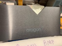
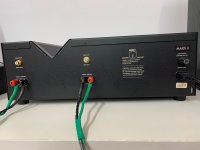
Having completed the DC offset and bias adjustments I gave the exterior of the amplifier metal case a good cleaning. I'm pleased to report that any blemishes are very slight and are not very noticeable at all.
Aragon 4004 - after cleaning
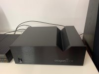
Aragon 4004 - part of the front face
Aragon 4004 - rear
So. The real test. I connected Thiel CS3.6 speakers to the amp and used a Meridian 208 as a CD sound source..
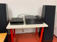
Playing Fade to Black from Dire Straits On Every Street was phenomenal. The Thiels sprang to life and this massive soundstage opened up in my workshop.
As I increased the volume the bass extension and control of the Thiels was as tight as it always was and at this point the family (and probably the neighbours) were beginning to notice.
I removed the amplifier metal cover and felt the output transistors. All nicely warm and no hot spots. A temperature probe revealed a surface average temperature of about 45°C (113°F) when the amp was working. The heat sinks were working nicely.
For the last week I've been playing all sorts of music - jazz, rock and classical. Even at low volumes there's great presence there.
The placement of the Thiels is terrible. They are too close together and too close to the walls. In a proper listening situation they need better distancing than that. But that's all I have room for in my workshop - or at least one end of it.
So there endeth a long period of restoration but it has been a great pleasure to bring such a solid nicely built amplifier back to life.
I remain grateful to the forum members who have participated in this thread for their continued help and advice. Much appreciated.
donf
Having completed the DC offset and bias adjustments I gave the exterior of the amplifier metal case a good cleaning. I'm pleased to report that any blemishes are very slight and are not very noticeable at all.
Aragon 4004 - after cleaning

Aragon 4004 - part of the front face

Aragon 4004 - rear

So. The real test. I connected Thiel CS3.6 speakers to the amp and used a Meridian 208 as a CD sound source..

Playing Fade to Black from Dire Straits On Every Street was phenomenal. The Thiels sprang to life and this massive soundstage opened up in my workshop.
As I increased the volume the bass extension and control of the Thiels was as tight as it always was and at this point the family (and probably the neighbours) were beginning to notice.
I removed the amplifier metal cover and felt the output transistors. All nicely warm and no hot spots. A temperature probe revealed a surface average temperature of about 45°C (113°F) when the amp was working. The heat sinks were working nicely.
For the last week I've been playing all sorts of music - jazz, rock and classical. Even at low volumes there's great presence there.
The placement of the Thiels is terrible. They are too close together and too close to the walls. In a proper listening situation they need better distancing than that. But that's all I have room for in my workshop - or at least one end of it.
So there endeth a long period of restoration but it has been a great pleasure to bring such a solid nicely built amplifier back to life.
I remain grateful to the forum members who have participated in this thread for their continued help and advice. Much appreciated.
donf
Beautiful and excellent functional layout along with the unique way they V notch it for the sinks. I should be able to find one eventually where I live most things pass by now and again. Beauty amps.
BTW do you know the size specs or 'VA' output rating of each transformer? When it comes to amplifiers thats one of the very first things I check for. A fat healthy PS.
BTW do you know the size specs or 'VA' output rating of each transformer? When it comes to amplifiers thats one of the very first things I check for. A fat healthy PS.
- Status
- This old topic is closed. If you want to reopen this topic, contact a moderator using the "Report Post" button.
- Home
- Amplifiers
- Solid State
- Aragon 4004 Mk2 restoration
