I have also a C-R-C configuration for the power supply which helps in reducing the hum...
Note that the R is done using 5A fuses but small 0,1 ohms power resistors or so can be used instead of fuses... The higher the resistor value is good to reduce the hum but at the expense of losing DC power supply voltage...
You can try removing only one channel signal cable at a time to isolate the problem. ( but with power off when removing the cable of course...).
Fab
Last edited:
Hi
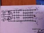
Here is a picture of my amp, see if I have done something wrong.
The cables to L/R chassie RCA comes from the copper rail not the softstart print.
Have hum with signalcables inn.
No hum with no silnalcables inn.
Have hum with shortcuted RCA plugs.
Groundloop?
Frank.
Here is a picture of my amp, see if I have done something wrong.
The cables to L/R chassie RCA comes from the copper rail not the softstart print.
Have hum with signalcables inn.
No hum with no silnalcables inn.
Have hum with shortcuted RCA plugs.
Groundloop?
Frank.
Last edited:
Hi
I notice that you have definitely at least one or more ground loop. The most obvious one being your RCA plug having the ground connected to the amp board while being also connected to "another" ground ( copper bar close to your soft start?). You should have only one ground path from your input signal. Also ensure that your RCA plug is isolated from chassis. You seem to have multiple ground points in your amp. You should use a star ground config to prevent the ground loops issue. There may be other issues too like why "ground' wires from your soft start circuit(or copper pad?) to your main power supply caps?
Fab
Last edited:
Yes the last thing is a problem you easily oversee and often is a problem with the cheaper rca's , which have flat spacers , instead of ones incaved ones which come standard with the more expensive ones(couple of bucks).
But just use some isolation tape or heatshrick on ithe place where the chassis could touch the outside of the rca, or just buy a bag of good isolators. And taking a lot of resistors is in my opinion adding noise. and if they act like a fuse they create extra thermal noise, but indeed is see ntc and ptc,' often use next to a voltage regulator and it works, but it' not my cup of tea. If the coolblock gets that hot something is built cheapo.
gr rich
I have been having similar hum issues with my Le Monstre. If you have a scope its worth looking at the waveform of your hum. If its a small spike at the start of the cycle - its a charging spike from your transformer. This is caused by the large first cap and the low resistance of the transformer. The transformer becomes a radio transmitter to this spike which means it can be picked up at any point in the amplifier on any wire or component. Its all but impossible to eliminate unless you remove the transformer from the case or shield it with silicon iron.
I have reduced mine by introducing resistance into the transformer to slow down the charging spike and reduce its size. I have achieved this with a 10R resistor on the primary and then 0.5R on each leg of the secondary. This has reduced the hum by about a half. The penalty is a loss of about 2V on each of the rails.
Hope this helps someone.
Shoog
Hi
I will isolate RCA and remove cable from copperail.
Cables from copperail to main powersupply caps is 0v and is conected on R/L side. Not a good stargrounding? Is better to have AC ground to chassi and make a goog stargrounding for for the rest of 0v. And try ( resistor in paralell with antiparalell diods between s.grounding and AC chassi ground) ?
Have also heard that push/pull amps board ground must have its own cable direct to s.grounding and not via power supply caps that I have done.
Shoog: See the trafo problem, I look at that.
Frank
Hi
...
Cables from copperail to main powersupply caps is 0v and is conected on R/L side. Not a good stargrounding? ...
Is better to have AC ground to chassi and make a goog stargrounding for for the rest of 0v. And try ( resistor in paralell with antiparalell diods between s.grounding and AC chassi ground) ?
...
Frank
Star ground means no other parallel ground path also (you have input RCA gnd wire to power amp board then to PS caps 0v and also in parallel with RCA metal return to copper rail ground then to PS caps 0v...).
Yes for the grounding arrangement to chassis.
To filter spikes you can probably add RC snubber in parallel with each diode of the diodes bridges.
Fab
Last edited:
Snubbers can help, but they wont solve the problem of a big low resistance transformer and massive first filter caps causing large charging spikes. This is rather like the radio interference generated by a spark bridging a gap - a crack like sound. The only way to solve it is to take the transformer away from sensitive circuits and signal wires (including earth wires) or reduce the charging spike which is causing the problem in the first place. Oversized transformers are not your friend in this context.To filter spikes you can probably add RC snubber in parallel with each diode of the diodes bridges.
However, you can take this as a point of general information, since the behaviour with and without signal cables plugged in points to it been a ground loop issue.
Shoog
http://www.diyaudio.com/forums/atta...r-cfa-vs-vfa-rumble-how-wire-up-power-amp.pdf
This pdf is a very well illustrated overview on to safely wire up a no-hum amplifier.
Refresh your knowledge.
This pdf is a very well illustrated overview on to safely wire up a no-hum amplifier.
Refresh your knowledge.
please help
Hello guys,
This year i managed to make some money to buy myself two trafos E+I 300VA@25+25v@5A bifilar secondaries windings for the a dual monos Jean Hiraga 30w "Super Class A amplifier". I want to make a separate 25-0-25V for the input and 30-0-30V just for the output tranies.
Wich solution is better for the best sound quality:
1. The schematic attached (one per single chanel) but with Mr Evil CM instead of the 0.22Ohm/25W resistors for the outputand another CM for the input.
2.The schematic attached as it is (one per single chanel) for the output and a separate Mr Evil CM for the input.
* Can i use a single CM for both inputs from a separate trafo (20+20VA)? Or i have to use separate CM for each channel?
*What is better to use: a separate trafo for CM of the input or take the AC current from the same trafo used for the input?
Attachments
1.Did anyone tried the Super class A with cap multiplier?
What differences have you noted between CM and a classic PSU (CLC recomended by Hiraga) in terms of sound reproduction (dynamics, clarity) and ripple?
I want to hear some impressions about this mod because i want to know in wich PSU to invest for this amp.
I'm interested in "Mr Evil Cap Multiplier", what do you all say?
2. Did anyone tried to do a second psu just for the input? What differences made?
3. What trannies should we use for the output stage because the 2sa/2sc pair are fake in my country and very hard to find?
Thanks in advance

View attachment 461577 Hi
Have done some change to my amp. Almost no hum, must nearer then 0.5m to speaker to hear it. 56db 10cm from speaker. 58db at tramsformator in amp.
Frank
How much db on 50 Hz and 100 Hz?
Nice building...
Big caps looks like Philips/BC caps !
WHat is the value and brand of the little alum bypass cap ?
Could such 30 W A from H. able to provide as much current than a Quad 909 ? (this last is a A/B, so I don't ask for the sound but the possibility to feed complex passive filter and instant current capability ?)
No envy to go for CLC filtering ?
Almost no hum, must nearer then 0.5m to speaker to hear it. 56db 10cm from speaker. 58db at tramsformator in amp.
Beautiful amp Frank
Regarding hum in Hiraga 30w class A and Le Monstre amps it is mostly because of the circuit being more sensitive to noise from the power supply lines than other types of amplifiers.
In other amplifiers the hum will come from poor grounding, so it is great to see that others have pointed this out.
But in Hiraga - it is also from the power supply.
You are on the right path to filter the power with CRC and possible CLC PS, so if you want to lower the hum even more, that is definitely a way to go.
In another thread on the Hiraga Class A we have also been discussing regulated supplys and something called "multiplied capacitor".
It seems that Mr. Hiraga himself knew about these and still decided to go with CRC and huge capacitors.
Please read more in this thread if you wish.
But still: beatiful stuff already.
Hi again bhpistorqintorpm: I got my pcb in 2013 so dont know.
damon1983: Im not sutre what you mean? ( :
Eldam: The big caps are F&T ( 100.000mF 40V ). The bypass is 10mF from RIFA ( PEG 124 YF 2100 Q ). I am runing it on a complex 3 way filter system and a 90db + speaker.
CLC filtering I have to look at.
Nrik: I look in to it.
damon1983: Im not sutre what you mean? ( :
Eldam: The big caps are F&T ( 100.000mF 40V ). The bypass is 10mF from RIFA ( PEG 124 YF 2100 Q ). I am runing it on a complex 3 way filter system and a 90db + speaker.
CLC filtering I have to look at.
Nrik: I look in to it.
Hi All,
First please note that I have not read the thread in detail so I may have missed something ... however, what I thought about saying was that I built some of these amplifiers some years ago (mainly the 8W Le Monstre) and found that they greatly benefitted from battery supply, i.e. a suitable low-noise "charging" circuit feeding batteries which is then closely connected with the amplifier circuit.
Also, in some cases when there was a bit of hum I found that placing small ferrite beads on the transistor pins could reduce the hum (borderline oscillation damping I guess) and as a second positive effect it also somehow "settled" the sound with improved detail, image focus, and tonal integration.
Good luck in your endeavors,
Cheers - Jesper
- Status
- This old topic is closed. If you want to reopen this topic, contact a moderator using the "Report Post" button.
- Home
- Amplifiers
- Solid State
- Hiraga 30W.