Agree, there's several doubtful capacitors there and C500 (in parallel with either C700 or C701) could also have a problem.
For checking possible transistor faults, the more useful voltage to measure is from ground to the DC output node, at the positive
terminal of those caps, also the junction of R500 & R501. This voltage should be close to half the supply rail at 32V, as shown.
If not, there is a more serious problem. As the total output capacitance is only ~1,000uF, the caps could be increased to at
least 2,200uF total, to gain a little bass response which must have been very thin, even with 15R speakers, which may have
been more common around 1970.
Feedback is taken from both sides of the output capacitors - that seems unusual but I guess it ensures safety if the cap fails.
The input summing stage is isolated for DC, so this should not cause DC offset problems. A leaky C505 though, could.
You don't say anything of the amplifiers's general condition but unless the amplifier has been completely refitted with new
electrolytics since it was manufactured, then it is long overdue.
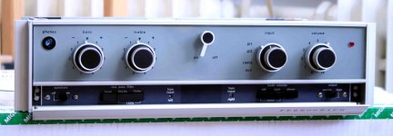
Here's a website for anyone interested in this series of amplifiers: Ferrograph Tape Recorders
BTW, I think both channels would be affected if either bridge rectifier failed.
There is only one power supply (65V) for both power amplifiers and the other
is a separate 42V supply for both preamplifiers and indicator lamp.
BTW, I think both channels would be affected if either bridge rectifier failed.
There is only one power supply (65V) for both power amplifiers and the other
is a separate 42V supply for both preamplifiers and indicator lamp.
Thank you for you answers!
that helps me I'will check it as soon as i have time and muse and i have to make myself clear if I will fix it because like Ian Finch said it could be a long overdue the amp is otherwise in a nice condition and i like it's look and how it's build and when I tested it i was thinking it's rather good sounding
best
hironimo
Attachments
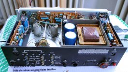
Nice pics. In the last, the 2 large electrolytic caps which pass through the chassis, have a bulge near their terminals. This is a sign of failure of the safety vent, even if they are still partly functional. If you look at the bottom cover plate, you may see evidence of electrolyte leakage below them, which would confirm an advanced state of breakdown. Replace those as a matter of urgency with a capacitor close to the diameter if possible. Since modern electrolytics are a fraction of the volume of these, that's not easy and you may need to buy new and smaller clamps as well, perhaps spoiling appearance if the insides are important to you.
A good catalogue with dimensions and full specs. is helpful, bearing in mind that length is not important whilst diameter is. This example is commonly available in several brands and may even fit. Terminals will not be identical but will still be fine for hand-wiring: SLPX472M080H3P3 Cornell Dubilier | Mouser
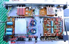
Actually, I'm surprised that all those blue "Philips" electrolytics seem to look ok. In this country, they were always the first parts to fail whilst in Europe - I see there is praise for them as long-lasting. Note that axial leaded capacitors like these are now scarce and expensive so it is necessary to check sources first. Beware the audiophile component specialists who want an arm and a leg for the simplest of parts such as these.
A good catalogue with dimensions and full specs. is helpful, bearing in mind that length is not important whilst diameter is. This example is commonly available in several brands and may even fit. Terminals will not be identical but will still be fine for hand-wiring: SLPX472M080H3P3 Cornell Dubilier | Mouser
Actually, I'm surprised that all those blue "Philips" electrolytics seem to look ok. In this country, they were always the first parts to fail whilst in Europe - I see there is praise for them as long-lasting. Note that axial leaded capacitors like these are now scarce and expensive so it is necessary to check sources first. Beware the audiophile component specialists who want an arm and a leg for the simplest of parts such as these.
- Status
- This old topic is closed. If you want to reopen this topic, contact a moderator using the "Report Post" button.
- Home
- Amplifiers
- Solid State
- Ferrograph F307