Hope nobody minds me starting a separate thread for this…
I'm simulating the JLH '69 Class A amp and have it outputting 0.5 Watt into a 4 Ohm speaker (Yes - purposely starting small and low output). I'd like to power it from a 5V wall wart power supply but I need know how to calculate how much current the amp is drawing and how much current the power supply needs will have to source.
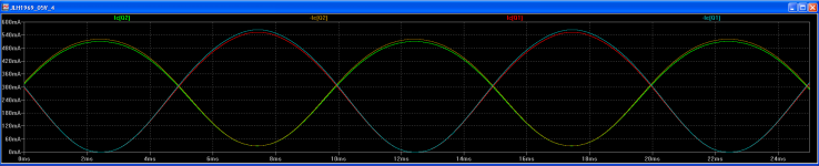
The sim below shows the current across the Collector and Emitter from the two output transistors peaking at about 570mA. It's pretty similar across the frequency range from 20Hz to 20K Hz and similar again with a square wave input.
So from that - how do I calculate or approximate the current requirements of a power supply for this amp or calculate the draw for the amp itself.
Thanks.
I'm simulating the JLH '69 Class A amp and have it outputting 0.5 Watt into a 4 Ohm speaker (Yes - purposely starting small and low output). I'd like to power it from a 5V wall wart power supply but I need know how to calculate how much current the amp is drawing and how much current the power supply needs will have to source.
The sim below shows the current across the Collector and Emitter from the two output transistors peaking at about 570mA. It's pretty similar across the frequency range from 20Hz to 20K Hz and similar again with a square wave input.
So from that - how do I calculate or approximate the current requirements of a power supply for this amp or calculate the draw for the amp itself.
Thanks.
Attachments
Your calculation seems right.
Thanks for the reply Eric - thing is, I haven't actually made any calculations. I'm just seeing approx. 570mA peak at the output in the sims.
If that's the highest current rating I need to be concerned with and I just need to spec a supply with enough headroom to cover any big transients then that's an answer I'll go with - just wanted to check though.
BTW - this will be mono.
Thanks again.
Best simulate or rather breadboard it, to see whether a 5V supply is even feasible with real parts operating away from their best linearity regions first, then read some tables on the amplifier and get some understanding of how a SEPP amp. operates and differs from other designs in class A.
The Class-A Amplifier Site - DC Voltages
2 amps bias is suggested for use with 4R loads at normal supply voltages like the recommended 27V. Given that even ideal efficiency of the design is only 25%, RMS output current x 5 would not be far off an appropriate bias figure. A calculated figure of 1.6A for full power into a 4R load is in reasonable agreement.
If you require 0.5W/4R, you obviously need a minimum 1.4V rms and this demands a min. 0.35A rms so bias is ~1,75A or the same 2A for practical purposes.
Whilst a "wall-wart" with 2A capacity should be feasible, one that runs at 2A or so continuously may not be easy to live with.
Last edited:
Please, watch this video
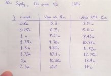
This will answer you....there you have a chart of power, voltage and impedance and supply current requirements.
https://www.youtube.com/watch?v=I3CUHoEbXvw
regards,
Carlos
This will answer you....there you have a chart of power, voltage and impedance and supply current requirements.
https://www.youtube.com/watch?v=I3CUHoEbXvw
regards,
Carlos
Attachments
Last edited:
abstractjuz, The output transistors draw virtually all the current so a simple approach is to note that you need 0.6V per o/p transistor to turn them on so you have 3.8V of your 5V power supply to drive the load. For a single rail amplifier the 3.8V is peak to peak which converts to 1.34v RMS. The current through your speaker will be V/R = 1.34/4 = 0.34 Amps RMS.
Add a bit for luck and for a single channel 1 Amp should be plenty and the 2A that e_fortier notes should be fine for a stereo pair.
This is an amplifier that is reported to lots lots of current to give of its best, but that's a very different situation from what you say is an early stage of just trying it out.
Good luck - you won't need it")
Add a bit for luck and for a single channel 1 Amp should be plenty and the 2A that e_fortier notes should be fine for a stereo pair.
This is an amplifier that is reported to lots lots of current to give of its best, but that's a very different situation from what you say is an early stage of just trying it out.
Good luck - you won't need it
If you require 0.5W/4R, you obviously need a minimum 1.4V rms and this demands a min. 0.35A rms
Can I ask how/where you got 1.4V RMS?
I understand that sqrt(0.5/4) = 0.353A
Thanks.
abstractjuz, The output transistors draw virtually all the current so a simple approach is to note that you need 0.6V per o/p transistor to turn them on so you have 3.8V of your 5V power supply to drive the load. For a single rail amplifier the 3.8V is peak to peak which converts to 1.34v RMS. The current through your speaker will be V/R = 1.34/4 = 0.34 Amps RMS.
Good luck - you won't need it
Ah - I think this answers the question in my previous post.
3.8V (peak supply) * 0.3535 = 1.34 V RMS.
Very helpful - thanks all.
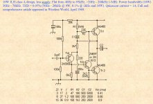
I do think we have a thread about the JLH 1969
Maybe two, or three.... this one was deeply explored...and till now a days remains a very good audio amplifier.
Here you have a link:
http://paul-kemble.tripod.com/sound3b.html
And one image too...
regards,
Carlos
Maybe two, or three.... this one was deeply explored...and till now a days remains a very good audio amplifier.
Here you have a link:
http://paul-kemble.tripod.com/sound3b.html
And one image too...
regards,
Carlos
Attachments
The JLH is a version of a single ended amplifier.
A single ended has a quiescent current and the maximum output is just a tiny bit less than that quiescent current.
The JLH modulates the quiescent current and we can expect the maximum output current to be around 1.5Times the quiescent current.
For normal single ended:
Maximum output power = Iq * Iq * Rload / 2 = 1*1*8/2 = 4W
For JLH
Maximum output power = Iq * 1.5 * Iq * 1.5 * Rload / 2 = 1.5*1.5*8/2 = 9W
The supply rail current is Iq = 1A. This is continuous while the amplifier is standing idle. The transformer and the PSU must be designed to tolerate this continuous current.
The supply rail current varies when an output current is delivered to the load.
Expect the variation to be very approximately plus 1.5Apk and minus 1Apk.
This gives a supply rail current when delivering maximum power of 1A+1.5Apk = 2.5Apk and changing to 1A - 1Apk = 0Apk for the other half wave of the maximum signal.
The PSU MUST be able to change it's current from 1A to 0A and from 1A to 2.5A to allow the amplifier to deliver it's maximum rating of 9W into 8r0 (the resistive version of 8ohms).
The maximum voltage at the output will be 1.5A * 8r0 = 12Vpk. But this is only available if the PSU and the amplifier have sufficient current capability to allow the dual requirement of 12Vpk and 1.5Apk to be delivered simultaneously.
Last edited:
Hi,
For a 5V supply with and output swing of +/- 1.8V
at best, lets call it +/-2.0V, into 4R, its clear 0.5A
would be more than adequate, and in reality about
0.33A is all you really would ever need, as basically
5V is simply too low to be a sensible supply voltage.
rgds, sreten.
For a 5V supply with and output swing of +/- 1.8V
at best, lets call it +/-2.0V, into 4R, its clear 0.5A
would be more than adequate, and in reality about
0.33A is all you really would ever need, as basically
5V is simply too low to be a sensible supply voltage.
rgds, sreten.
- Status
- This old topic is closed. If you want to reopen this topic, contact a moderator using the "Report Post" button.
- Home
- Amplifiers
- Solid State
- Calculating current draw of SS Class A amp