Laser printers you are using for toner transfers
Hi everyone,
I don't mean to hijack this thread with my request. Since a lot of etching is done by members on this thread and other threads, I would like to enquire what brand of laser printer you are using and the model.
I have been searching websites and found out that some lasers are dreadful at transfers and some are excellent.
So, if you could point me in the right direction, I would be mighty grateful, and hopefully some of the laser printers will be fairly recent (2015-2016), as it is getting hard to find earlier models.
Myles
Hi Myles,
Terry (Still4given) would be the perfect person to answer your query, as I think he is the biggest consumer of laser toners and etchants
 .
. I generally use photo-resist method, which if done properly does provide excellent results even with tighter clearances. sometimes I fail, even with this method
. Thimios had promised a tutorial on this method , i might have missed it.
 reg
prasi
Yes prasi ,an analytic tutorial has been published in destroy-x super A thread,i will try to do a new tutorial with pictures.Hi Myles,
Terry (Still4given) would be the perfect person to answer your query, as I think he is the biggest consumer of laser toners and etchants
I generally use photo-resist method, which if done properly does provide excellent results even with tighter clearances. sometimes I fail, even with this method
reg
prasi
This photo-resist method is away better!
My last amplifiers, like Valery Zero distortion modular and astx SA1015 used commercial pcb offered to me by good friends.
I want to thank everyone for all your pcb and parts offers.
Last edited:
I use an HP Laserjet P1102w printer. It works very well and is reasonable in price.
Don't try Brother printers. They need a lot more heat.
I believe photo etch is better but the boards are expensive. I buy my boards for less than $1 each so it makes the little bit of extra work worth it to me.
Don't try Brother printers. They need a lot more heat.
I believe photo etch is better but the boards are expensive. I buy my boards for less than $1 each so it makes the little bit of extra work worth it to me.
I use an HP Laserjet P1102w printer. It works very well and is reasonable in price.
Don't try Brother printers. They need a lot more heat.
I believe photo etch is better but the boards are expensive. I buy my boards for less than $1 each so it makes the little bit of extra work worth it to me.
Samsung SCX-4521F works perfect with original toner.
Actually it's the paper that's most important. Some papers are terrible.
Samsung SCX-4521F works perfect with original toner.
Actually it's the paper that's most important. Some papers are terrible.
I use shelving paper for the medium. Saves scrubbing off the paper.
I am running mine at 25v rails right now and the biggest thing I notice is a whole lot less heat generated! Even at 180mA bias, the quiescent heat output is under 9w so the heatsink is staying pretty cool. This also means it can work real well with two 24v SMPS bricks in series.
My 25v rail supply consists of a 400VA Antek toroid and CRC consisting of 33mF qnty 4 x 0.47R in parallel and 33mF caps. The ripple at the power supply is only 7mV with 180mA bias. Speakers are dead quiet with no signal.
Question for Hugh: is there any advantage in running this amp in Class A at say 1.3 amps bias? Can it even handle it assuming adequate heat removal via heatsink and PSU is designed for large continuous current?
65w of heat generated could easily be removed with fan on the heatsink,.
If I back it off to 100mA, it will be real cool.
Last edited:
Eric,
I have found that the larger electro does not improve bass. 100uF is just fine..... and you can use small ones with high ripple factor, 100KHz rating and 63VW for low cost. Generally, I use Nichicon, but in N America the biggy is CDE.
Cheers,
Hugh
The 100uf one you are talking about is C4 (1000uf 6v3) on 4.3 revison schematic?
Marc
hi hugh
what is the rated voltage of the below capacitors @ 42vdc rail..
i ask so that we can minimised the diameter of the capacitor.
C7 1000uF
C6 100uF
C4 47uF
C3 22uF
Dacs, the designations and values here do not match the schematic. For example, C4is a 1000uF part on your schematic. The VAS bootstrap (C6) should be a 63V rated part. The other electros are low voltage 16V or 25V devices.
Hi Dacz,
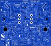
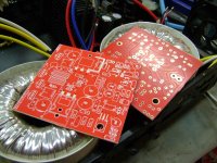
Very nice pcb, beautifully laid out - my thanks! One suggestion; if you put the large outputs central on the pcb, you can fit the pcb exactly midpoint along the heatsink. The amp looks a bit more tidy but it's not essential and certainly does not change the operation.
I am with Ranchu, his suggestions are my suggestions too! I generally like to use a film cap for C1, 1.5uF is just fine. Electrolytics are not quite as good, even when they are polarised by a couple of volts like this amp input stage. If you use 42V rails, 50VW caps are right on the limit (80%) so there is good sense on using 63VW as they are not much bigger and then offer a lot of upside to the rail voltage. Since outputs can just support up to 48V rails, this makes sense.
As for Class A, I do not like the idea much. I think the sound would be different, but consider that since the upper nmos does not turn off and therefore the cross over point is somewhat blurred, I cannot see the advantage in ensuring the lower npn never turns off. To achieve this, the currents would be horrific; to prevent the npn turn off at higher output (no higher than 65W into 8R, 32.3Vpeak) the quiescent current with 42V rails (no sag at all BTW) we have to give a quiescent current of 4.5A. This mandates 182W dissipation in the nmos, and 180W dissipation in the C5200. These are impossible to sustain; you'd need at least of 480W dissipation in EACH of the two output devices to maintain this dissipation over decent a lifespan for the amp. Even at 65W I see the H5 harmonic at -96dB, compared to the quiescent at 120mA where it's -84dB.
Essentially, this amp is optimised for Class AB, and if you use to Class A, you need a different topology, more like the JLH, which is actually designed for Class A (but gets VERY hot for low output!). High dissipation in output devices reduces MTBF; effectively an increase of 11C halves the life. So if the device operates at 58C, say 33C more than 25C, the life will be almost 2exp3 less, which is 8 times. This is pretty steep, so you have to be careful.
Cheers,
Hugh
Last edited:
The 100uf one you are talking about is C4 (1000uf 6v3) on 4.3 revison schematic?
Marc
No, I was talking about C6 (Bootstrap cap) from the schematic on post no.1354
No, I was talking about C6 (Bootstrap cap) from the schematic on post no.1354
Sorry for no quote.....the question was for Hugh related to a previous post where he said 100uf is enough....
Thanks, farjon!
Ok. If you have any doubts, comments or "fixes" during mounting, please call me. This is version 1.0...
And thanks for your mounting. My lab is temporarily inactive.
Regards.
- Home
- Amplifiers
- Solid State
- Very simple quasi complimentary MOSFET amplifier