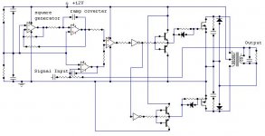
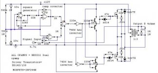
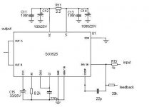
This is the Schematic of CAR AMP directly operated from +12V Battery. This is based on PWM class_d amplification
Switching frequency is 210KHz
The frontend includes
1 Square wave oscillator
2 Ramp converter
3 comparator
4 error amp
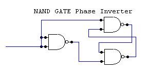
5 inverter buffer
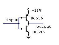
6 Discrete gate driver
7 mosfet output stage
8 Audio Transformer with INterleaved BiFillAr windings
Switching frequency is 210KHz
The frontend includes
1 Square wave oscillator
2 Ramp converter
3 comparator
4 error amp
5 inverter buffer
6 Discrete gate driver
7 mosfet output stage
8 Audio Transformer with INterleaved BiFillAr windings
Attachments
It might be working but not with an ordinary audio X-former.
To work properly this transformer has to have some very special properties. Low losses at very high frequencies and low THD (down to very low frequencies) to name just two that are difficult to achieve at once.
This transformer would definitely be large and expensive.
The combination of an SMPS and a switching amp with higher rail voltages would definitely be smaller and cheaper.
Regards
Charles
Well, if you like designing transformers, then this circuitry is somehow charming ") )). Also the outputfilter can be integrated to this transformer.
)). Also the outputfilter can be integrated to this transformer.
But it is true. The size of the Transformer may be large. It looks like an amp for about 100W. The transformer has to put through this also at low frenquencies.... say 20Hz.
If we look at a 50Hz transformer for 100W and now reduce the frequency...
hmm... additional the transformer should also work up to 30kHz. You probably would use ferrites as magnetic materials. Good high frequency properties but poor saturation.
...doubling the size again.
On the other hand:... just some thoughts.....
May be you can work with materials which have less good high frequency properties than ferrites but higher saturation flux density, because the 210kHz will not cause much flux density (small time-voltage-product if compared to the low frequency audio signal which will be the critical point for saturation....) I did not calculate this in detail.
May be "iron powder" or "Coolµ"
will work.
Best choice would be something exotic (but hard to get and more expensive) which provides high flux and very low losses: amorphus metals (i.e. from VAC in Germany)
Also if you consider that the power crest factor of normal music programm is around 1:3 you might be able to design with less copper ....
...interesting, it might become better than expected first....!!!!!!!!!
But anyway, the transformer will heavily influence the sound and stability of the amp. If you are really skilled in designing inductive components..
..not only magnetics, but also hf-losses in windings..., then you could try it.
Otherwise you should keep hands off.
...or try to get details about the construction of the original transformer and copy it....
)). Also the outputfilter can be integrated to this transformer.But it is true. The size of the Transformer may be large. It looks like an amp for about 100W. The transformer has to put through this also at low frenquencies.... say 20Hz.
If we look at a 50Hz transformer for 100W and now reduce the frequency...
hmm... additional the transformer should also work up to 30kHz. You probably would use ferrites as magnetic materials. Good high frequency properties but poor saturation.
...doubling the size again.
On the other hand:... just some thoughts.....
May be you can work with materials which have less good high frequency properties than ferrites but higher saturation flux density, because the 210kHz will not cause much flux density (small time-voltage-product if compared to the low frequency audio signal which will be the critical point for saturation....) I did not calculate this in detail.
May be "iron powder" or "Coolµ"
will work.
Best choice would be something exotic (but hard to get and more expensive) which provides high flux and very low losses: amorphus metals (i.e. from VAC in Germany)
Also if you consider that the power crest factor of normal music programm is around 1:3 you might be able to design with less copper ....
...interesting, it might become better than expected first....!!!!!!!!!
But anyway, the transformer will heavily influence the sound and stability of the amp. If you are really skilled in designing inductive components..
..not only magnetics, but also hf-losses in windings..., then you could try it.
Otherwise you should keep hands off.
...or try to get details about the construction of the original transformer and copy it....
reply
Thanx for ur interst!
1 The transformer itself has very high Inductance which acts as a filter for switching frequency
2 The whole audio quality is dependent on transformer .
3 I have build this amp rating 400WRMS using only 6 mosfets at both side drives.
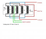
The transformer has following details:
Frequency response=20Hz t0 18Khz Flat
Core used=Cold Rolled Nickel Grain Oriented E-I Iron core which is used in audio transformers.
Cross section area of bobbin is 2 X 2 = 4 Sq inches for use in 500W power handling.
The transformer size is 5"H x 6"W X 2"D
The winding ratio is 1:3
I have used interleaved winding along with Bifillar windings to get maximum high frequency response.
construction is as follows:
Take 2 X 17SWG wires and wind them together i.eBiffilar winding upto 56 turns and then wind secondary 180 turns of single 16SWG wireand then again wind 2 X 56 turns of SWG17 wires in biffillar technique.
NOW see this diagram for connection
Thanx for ur interst!
1 The transformer itself has very high Inductance which acts as a filter for switching frequency
2 The whole audio quality is dependent on transformer .
3 I have build this amp rating 400WRMS using only 6 mosfets at both side drives.
The transformer has following details:
Frequency response=20Hz t0 18Khz Flat
Core used=Cold Rolled Nickel Grain Oriented E-I Iron core which is used in audio transformers.
Cross section area of bobbin is 2 X 2 = 4 Sq inches for use in 500W power handling.
The transformer size is 5"H x 6"W X 2"D
The winding ratio is 1:3
I have used interleaved winding along with Bifillar windings to get maximum high frequency response.
construction is as follows:
Take 2 X 17SWG wires and wind them together i.eBiffilar winding upto 56 turns and then wind secondary 180 turns of single 16SWG wireand then again wind 2 X 56 turns of SWG17 wires in biffillar technique.
NOW see this diagram for connection
Attachments
keep it up
hi
great to see your design , and then the effort you have put in designing your post
since it's transformer dependant and my loudspeaker drivers are coil dependant _ the winding s are the only area where my knowledge lies , (stayed away from smps _ leave alone class _ d though have a pro signal generator , scope etc )
- at the end sealing the transformers _with something like dr becks high - q sealing compond , this will stop the windings from starting to - sing them selves at higher frequencies !
this can be used in passive c/o s , too for those who have - singing c/o s !
also bi filiar may be diffcult to wind together tightly by hand , you could try a coil winding machine from bangalore , i can send you the co details , they have winding machines for all types of puposes which are - cnc - controlled (programmable) for rs 60,000 / -
one dynacord amp (not class - d ) ive repaired had a torroid output transformer the frequency responce was just amazing
suranjan
THANX FOR ENCOURAGEMAENT!
Thanx for comments
I donot wind the transformers with my hand !
I have selfmade winding machine which can be used to wind
MULTIFILLAR windings.
I am already using "dr becks high - q sealing compond "
along with SILICONIX TRANSFORMER VARNISH COMPOUND
This great combination provides dead vibrations ONLY!
CAN i get the DYNACORD schematic from u.
Even if I like this circuitry I have doubts that it will deliver 400Wrms into 4 Ohms.
Let's make a rough estimation.
12V from the Battery given in pos and neg direction to 56turns.... secondary side has 180 turns... ok from an ideal transformer we could get about 38V peak, from a real transformer... may be 35Vpeak.
This means 24.75Vrms ==> 153Wrms into 4 Ohms....
Even if we estimate that the amplifier will be driven at a battery which is beeing charged from the running engine we could calculate with 14V battery.... about 208Wrms...
But 400W or even 500W??????

- Status
- This old topic is closed. If you want to reopen this topic, contact a moderator using the "Report Post" button.
- Home
- Amplifiers
- Solid State
- Class_D PWM CAR AMP