Common source means the source is at "common" potential, ie AC grounded, ie wired to a power supply rail. It's your usual rail to rail opamp output stage.
Common drain means the usual follower.
Features of common source in the context of audio amplifiers:
Only advantage: you get a little bit more output voltage swing, but a follower can do that via the magic of bootstrapped driver supplies, so not really an advantage. Also in the last 5 volts the output devices get really slow, which means compensation headache, so do you really want those last 5 volts?
With VDMOS and BJTs, the back of the transistor is the drain/collector, so this now has high-quality, high-Q capacitance with the heatsink. With LDMOS, the back is the source, so in common source it's wired to the power rail anyway, so a bit of extra decoupling capacitance doesn't matter.
In a follower stage, bias is simple, just put a constant voltage between your two bases/gates. In a common source this bias voltage that must stay constant is now split in two halves that must have a constant sum. Also the driving signal must be split. This usually means bias will be less stable. But it also means when it comes out of clipping, one device is very much ON, well saturated and slow, and its driver, which is usually just a resistor, is squeezed between its base/gate and the rail, so it will not pull put that gate charge very fast. The other device is off with max Vds, so it is super fast, it will turn on before the other turns off, so you get a cross-conduction spike when it comes out of clipping. If you want to observe its clipping behavior on a scope, make sure the frequency isn't too high... This doesn't happen on follower stage if the gate resistors are low enough. Since both gates are pretty much tied together, the transistor that has to turn on will patiently wait for its turn until the driver has sucked the gate charge out of the one that must turn off. Unless of course gate resistors are too high, in which case it will also cross-conduct.
...and the winner is...
In a follower stage, when the transistors run out of juice at HF, gate drive current goes from the gate to the output through the parasitic capacitance. So you get a somewhat limp HF zero, mitigated by Cgd, so not zero phase shift, but still nice.
In a common source stage, gate drive current goes through Cgd into the output, but it's an inverting topology, so this gate drive current is the wrong polarity. This means you don't get just one pole, you get two poles thrown in for the same price, with clean 180° phase shift.
This kind of discussions, sadly reappearing too often, remind me of:
How many angels can dance on the head of a pin? - Wikipedia
Definitely some pin-headed angel dancing.
Dearest Peufeu,
I publicly reiterate my thanks for your great effort in developing the ideas from Hephaïstos on LTMD, which allowed me to take my own reckless dive on this realm of experience. Flawed as they may be, my humble experiments sound great to me.
Post #1.
Secondly, another common-source amp is the famous SONY TA-5650 VFET amp, whose input section I also modded to a putative LTMD, cascoded CFP sub-circuit, with the same sonic effect.
Thirdly, the sonic effects of the LTMD circuits are better perceived in the time domain, so do not focus on frequency related distortions to negate its obvious perceptual effects. Think about a better distribution of musical energy in the time domain, which produces enhanced dynamic contrasts, attacks, decays (time) and imaging (space), amongst others.
Lastly, being this forum devoted to "Do It", please try it, before opining.
I love you All,
M.
I publicly reiterate my thanks for your great effort in developing the ideas from Hephaïstos on LTMD, which allowed me to take my own reckless dive on this realm of experience. Flawed as they may be, my humble experiments sound great to me.
Post #1.
The AMNESIS amp: a good amplifier, like a gentleman, has no memory.
First of all, big thanks to Hephaïstos (ascended Master), to Peufeu, to Douglas Self, to uncle Charlie, DestroyerX, and to all those that investigate on thermal memory distortion and finally to everyone who is willing to help me here.
Secondly, another common-source amp is the famous SONY TA-5650 VFET amp, whose input section I also modded to a putative LTMD, cascoded CFP sub-circuit, with the same sonic effect.
Thirdly, the sonic effects of the LTMD circuits are better perceived in the time domain, so do not focus on frequency related distortions to negate its obvious perceptual effects. Think about a better distribution of musical energy in the time domain, which produces enhanced dynamic contrasts, attacks, decays (time) and imaging (space), amongst others.
Lastly, being this forum devoted to "Do It", please try it, before opining.
I love you All,
M.
Thanks Pierre for the writeup.
Thanks Maxlorenz for another example to look at.
This is DIY, unusual circuits should get more attention just for the fact that they deviate from the norm and there might be something to learn there, as well as the fun of doing something differently.
Why?
What we're discussing is quite different from a typical amp. The driver stage voltage swing is much reduced, only 2V p-p swing or less, because the output stage contributes voltage gain. I'm simulating something and it only needs half an amp of bias to deliver more than 50V p-p without switching. The outputs never turn off.
edit: the outputs seem to remain on (milliamp current) with more than 50V p-p out. But they do switch off in clipping.
Thanks Maxlorenz for another example to look at.
This is DIY, unusual circuits should get more attention just for the fact that they deviate from the norm and there might be something to learn there, as well as the fun of doing something differently.
Definitely some pin-headed angel dancing.
Why?
What we're discussing is quite different from a typical amp. The driver stage voltage swing is much reduced, only 2V p-p swing or less, because the output stage contributes voltage gain. I'm simulating something and it only needs half an amp of bias to deliver more than 50V p-p without switching. The outputs never turn off.
edit: the outputs seem to remain on (milliamp current) with more than 50V p-p out. But they do switch off in clipping.
Last edited:
I could not have explained better my preference for common drain topologyCommon source means the source is at "common" potential, ie AC grounded, ie wired to a power supply rail. It's your usual rail to rail opamp output stage.
Common drain means the usual follower.
Features of common source in the context of audio amplifiers:
Only advantage: you get a little bit more output voltage swing, but a follower can do that via the magic of bootstrapped driver supplies, so not really an advantage. Also in the last 5 volts the output devices get really slow, which means compensation headache, so do you really want those last 5 volts?
With VDMOS and BJTs, the back of the transistor is the drain/collector, so this now has high-quality, high-Q capacitance with the heatsink. With LDMOS, the back is the source, so in common source it's wired to the power rail anyway, so a bit of extra decoupling capacitance doesn't matter.
In a follower stage, bias is simple, just put a constant voltage between your two bases/gates. In a common source this bias voltage that must stay constant is now split in two halves that must have a constant sum. Also the driving signal must be split. This usually means bias will be less stable. But it also means when it comes out of clipping, one device is very much ON, well saturated and slow, and its driver, which is usually just a resistor, is squeezed between its base/gate and the rail, so it will not pull put that gate charge very fast. The other device is off with max Vds, so it is super fast, it will turn on before the other turns off, so you get a cross-conduction spike when it comes out of clipping. If you want to observe its clipping behavior on a scope, make sure the frequency isn't too high... This doesn't happen on follower stage if the gate resistors are low enough. Since both gates are pretty much tied together, the transistor that has to turn on will patiently wait for its turn until the driver has sucked the gate charge out of the one that must turn off. Unless of course gate resistors are too high, in which case it will also cross-conduct.
...and the winner is...
In a follower stage, when the transistors run out of juice at HF, gate drive current goes from the gate to the output through the parasitic capacitance. So you get a somewhat limp HF zero, mitigated by Cgd, so not zero phase shift, but still nice.
In a common source stage, gate drive current goes through Cgd into the output, but it's an inverting topology, so this gate drive current is the wrong polarity. This means you don't get just one pole, you get two poles thrown in for the same price, with clean 180° phase shift.

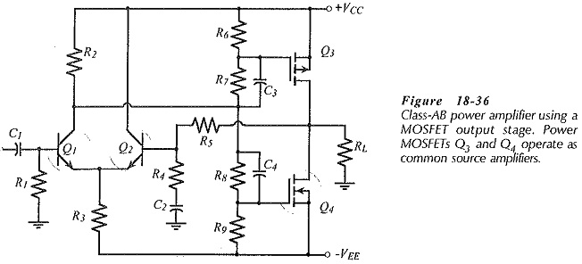
That`s not a common source output stage. Amplifier topology can be too elusive to grasp and easy to end up with a confused explanation. It would be more fruitful to concentrate on the attempt to understand the existing terminology instead of inventing a lot of nonsense.
Bucks Bunny quoted the exact correct definition of common source:
Originally Posted by peufeu View Post
Common source means the source is at "common" potential, ie AC grounded, ie wired to a power supply rail. It's your usual rail to rail opamp output stage.
If you think this it is wrong, please explain why or how?
Jan
BTW There's a whole book about no-global loop feedback amplifiers and how to avoid or cancel memory distortion in amplifiers:
https://www.amazon.com/Audio-Power-...keywords=arto+kolinummi&qid=1617784819&sr=8-1
... that there are other errors to be considered in amplifier design, which do not receive enough attention. In this study, Dr. Kolinummi analyses many sources of distortion and measurement methods. His focus is specifically on dynamic and transient errors, which are not normally considered in measurements, and what Kolinummi calls ‘memory errors’. ...
Jan
Attachments
Last edited:
BTW There's a whole book about no-global loop feedback amplifiers
Yes, I bought it, it's a good book, recommended!
BTW is the author around here? I'd like to ask a question about how he got to lower THD in the crossover region by paralleling more output devices (it's on page 220)...
I publicly reiterate my thanks for your great effort in developing the ideas from Hephaïstos on LTMD, which allowed me to take my own reckless dive on this realm of experience. Flawed as they may be, my humble experiments sound great to me.
hehe, thanks

Another example of "memory" is charge traps in FETs, when it has impurities in the interface (I think it's between the channel and oxide) that traps charge so it will take longer to turn off depending how far it went into the "on" region just before. I think Nelson Pass stumbled on something like that, I don't have a link but I remember a topic here where he'd found a batch of PMOS that had a weird rise in THD at some midband audio frequency.
The output stage impedance and the load impedance can be seen as constituting a voltage divider.I'd like to ask a question about how he got to lower THD in the crossover region by paralleling more output devices (it's on page 220)...
The more output devices working in parallel as voltage followers, the less is the output stage impedance and the less is the effect of its non-linearity on the output voltage.
The non-linearity of a single push-pull pair output stage in open loop is clearly irregular, mainly due to crossover distortion. It is much more smooth when three push-pull pairs are in parallel.
See Douglas Self "Audio Power Amplifier Design" sixth edition, page 269, Figure 10-17.
Last edited:
Yes, but.
Transconductance of BJTs is proportional to current.
So, for the same bias current, three devices running at bias I/3 will have the same transconductance as one device running at bias I. If emitter resistors are adjusted according to bias current, then they also scale the same way...
So you end up with the same transconductance no matter how many devices, if the same total bias current is used
I just messed with it in Spice, and the simulator agrees. I can get the exact same crossover with one pair of MJL4302/3281 or three.

However, with one device, at 100mA, the optimal value for Re is not practical, it is too low, like 50 mOhm, it'll run away and smoke. With three devices at 30mA each, it is a much more practical 0.33R, which means no smoke, which is always nice lol. So if you use one device, and you want an emitter resistor value high enough to avoid runaway, then you have to lower the bias to something like 33mA, and that narrows the crossover and increases distortion. Keeping the bias at 100mA with one pair of without runaway requires a resistor that is too, and you get gm-doubling.
So the crossover is the same whether there is one pair of transistors, or three pairs in parallel, when the total bias is the same, and the resistors are adjusted to the optimum value for this bias, and the resistor value allow actual implementation of the circuit without runaway.
However, using more devices allows to increase the total bias while keeping the optimum resistor values without getting thermal runaway, and that does widen the crossover and results in lower distortion.
But there are two variables at play: number of devices, and bias. And it's the bias that matters, what using more devices does is just to allow a higher bias to be used while keeping the optimum resistor values.
And, unfortunately, in the chapter, he doesn't give details about that. I suspect he uses a constant bias per device pair, so the total bias is proportional to the number of devices, in which case the distortion effects come from the increased bias, but the fact it works without smoking comes from the number of devices.
Transconductance of BJTs is proportional to current.
So, for the same bias current, three devices running at bias I/3 will have the same transconductance as one device running at bias I. If emitter resistors are adjusted according to bias current, then they also scale the same way...
So you end up with the same transconductance no matter how many devices, if the same total bias current is used
I just messed with it in Spice, and the simulator agrees. I can get the exact same crossover with one pair of MJL4302/3281 or three.
However, with one device, at 100mA, the optimal value for Re is not practical, it is too low, like 50 mOhm, it'll run away and smoke. With three devices at 30mA each, it is a much more practical 0.33R, which means no smoke, which is always nice lol. So if you use one device, and you want an emitter resistor value high enough to avoid runaway, then you have to lower the bias to something like 33mA, and that narrows the crossover and increases distortion. Keeping the bias at 100mA with one pair of without runaway requires a resistor that is too, and you get gm-doubling.
So the crossover is the same whether there is one pair of transistors, or three pairs in parallel, when the total bias is the same, and the resistors are adjusted to the optimum value for this bias, and the resistor value allow actual implementation of the circuit without runaway.
However, using more devices allows to increase the total bias while keeping the optimum resistor values without getting thermal runaway, and that does widen the crossover and results in lower distortion.
But there are two variables at play: number of devices, and bias. And it's the bias that matters, what using more devices does is just to allow a higher bias to be used while keeping the optimum resistor values.
And, unfortunately, in the chapter, he doesn't give details about that. I suspect he uses a constant bias per device pair, so the total bias is proportional to the number of devices, in which case the distortion effects come from the increased bias, but the fact it works without smoking comes from the number of devices.
Last edited:
You meant this gain vs frequency shelving (MOSFET rules, formulas and guidelines post#112)?I think Nelson Pass stumbled on something like that, I don't have a link but I remember a topic here where he'd found a batch of PMOS that had a weird rise in THD at some midband audio frequency.
AFAIK NP said all P-channel from Vishay (including Siliconix and IR) behaves similarly, but not including those produced by Harris, Intersil, Fairchild or Samsung. And remarked :
As a practical matter, I simply don't use IR P channel parts in Common-Source gain stages if I can help it. I have not had any dificulty with Common Drain applications, but then of course it would be far less noticeable there.
Last edited:
Good reasoning. But for a mutliple push-pull pairs of an output stage, it is normal that each pair is set at the optimal bias. The better linearity they provide comes at a price : for three pairs instead of one, three times the quiescent current.And, unfortunately, in the chapter, he doesn't give details about that. I suspect he uses a constant bias per device pair, so the total bias is proportional to the number of devices, in which case the distortion effects come from the increased bias.
You meant this gain vs frequency shelving (MOSFET rules, formulas and guidelines post#112)?
Yes! Great digging!
Good reasoning. But for a multiple push-pull pairs of an output stage, it is normal that each pair is set at the optimal bias. The better linearity they provide comes at a price : for three pairs instead of one, three times the quiescent current.
Yeah but "optimal bias" depends on the resistor (and vice versa) so you can still use more devices with the same total bias current by increasing the resistor. That would be a benefit if that allows you to pick the optimum emitter resistor value that avoids thermal runaway. Plus you get more SOA.
1 pair at 100mA (black) vs 3 pairs at 33mA each (red/blue) all with 0R33 resistors.
Plot 1 is gm, there is gm-doubling, but who cares.

Plot 2 is the base current, there is something suspicious.

Plot 3 is d(drive current)/d(output current) which is a bit like the inverse of the instantaneous current gain of the whole stage.

The one that has gm-doubling also has much much worse drive current. Note this is on a simulated 10kHz signal because the effect depends on capacitance, so it's not visible on a DC plot.
I didn't think there was an example of this using BJTs; turns out there is, and more than one. I'm referring to the amplifiers by Musical Fidelity, designed by the late Tim de Paravicini. He used common-source and common-emitter outputs. The one that I'm attaching uses BJTs in quasi-complementary topology (but the CFP is on the positive rail to make a common emitter).In a follower stage, bias is simple, just put a constant voltage between your two bases/gates. In a common source this bias voltage that must stay constant is now split in two halves that must have a constant sum. Also the driving signal must be split. This usually means bias will be less stable.
Attachments
Last edited:
The common emtter/collector/base amplifier stage consists of one amplifying device where the common input/output terminals are referred to ground rather than balanced to ground.
What (the hell) is memory distortion? What causes memory distortion? How can memory distortion be "canceled"?
What (the hell) is memory distortion? What causes memory distortion? How can memory distortion be "canceled"?
- Status
- This old topic is closed. If you want to reopen this topic, contact a moderator using the "Report Post" button.
- Home
- Amplifiers
- Solid State
- cancelling memory distortion ?