Pan
The C-Audio GB402 was made by C Audio after they were bought by Harmon International. Schematics for most of the earlier C Audio amplifiers are on the "Schematicsunlimited" web site. The site does not contain a schematic for the GB402. I suspect that only Harmon have the schematic for the GB402.
However all other C Audio amplifiers, and possibly/probably the GB402 use the same driver circuit ( with different rail voltages ) and very similar input circuits, protection and soft start circuits. The only real difference is that earlier amplifiers used Hitachi mosfets in the output stage. Then C Audio changed to BUZ and Exicon output mosfets and in some later amplifiers to BJT's. The Pulse series also varied the rail voltage.
I am attaching for you a spec sheet for the GB402. It contains Harmans contact details. Maybe they will release a copy of the schematic.
I own a lot of C Audio amplifiers and I have repaired a lot of them. If you can not find a schematic or if you need help to test voltages let me know and I will help if I can.
Don
Attachments
Thanks Dan,
Thank You for your GB spec sheet. I am not very familiar with Audio and i don't realize the GB series they are produced after they were bought by Harman International. I ben to the "Schematicsunlimited" web site and and I could not find any information on the GB series.
Regards
Pan
Thank You for your GB spec sheet. I am not very familiar with Audio and i don't realize the GB series they are produced after they were bought by Harman International. I ben to the "Schematicsunlimited" web site and and I could not find any information on the GB series.
Regards
Pan
Pan
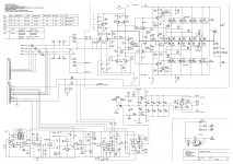
I looked at the schematic in the above post and it is as I expected. The amplifier uses the same input, second stage and pre-driver circuit but a slightly revised driver stage as the output devices have been changed from those on earlier models and a revised protection circuit. The schematic gives you the expected voltage drops across each resistor in the whole driver circuit which will help fault detection.
If you check the C Audio SRX range and the XR3801 in Schematicsunlimited you will find along with the amplifier schematics a complete description of the amplifier design and workings.
Don
Hi Sajti ,
Thank You for your 402 schematic attachment . I am not realising that the Crown XLS-402 is the same with GB402. Unfortunately the attachment as ".png" it is not
very clear. Please can you send me a PM, as a pdf ?.
Thankyou for your help.
Regards
Pan
Hi,
pdf version attached.
Sajti
Attachments
From experience. when these blow, just pull all active devices and replace them. replace the speaker relays too. you will most likely find a large % of bad/blown devices and I wouldn't trust whats left. the small transistors are not expensive so why risk it? the speaker relays are pretty crappy, when an output device fails, the relay overheats and the internal contacts bend and warp and short out.
a really cheap crappy design IMHO
a really cheap crappy design IMHO
Hi
It is normally a good idea to replace all cheap transistors but the problem with replacing all the small transistors is that non of the input stage, second stage or pre driver stage transistors are available now. You can use replacements but they will all have higher capacitance.
I would therefore try running the amp on a low voltage and try to see where any problems are.
When I repair a C Audio amp I replace the soft start circuit fuse with a 100w light buld connected accross the fuse holder and start the amp that way. This way the amp runs at about half voltage and if there are any large current draws from the amp most of the mains current will go to the 100w lamp which will glow brightly. When all faults are repaired the light bulb becomes dim.
Don
Hi to all of you,
Problem solved with your help.
R14 on Q3 base it was cut but with no visible site of damage, and
C9 on protection circuit it was dead.
Sajti,
Thanks for the schematics, it was very helpful.
Don,
Thanks for your detailed explain instructions.
You was right about the small spares.
Regards
Pan
Problem solved with your help.
R14 on Q3 base it was cut but with no visible site of damage, and
C9 on protection circuit it was dead.
Sajti,
Thanks for the schematics, it was very helpful.
Don,
Thanks for your detailed explain instructions.
You was right about the small spares.
Regards
Pan
- Status
- This old topic is closed. If you want to reopen this topic, contact a moderator using the "Report Post" button.
- Home
- Amplifiers
- Solid State
- Help to fix C-Audio GB402 Amplifier