Hi Aniket, if you in the mood to spend more money, use Panasonic FC electrolytics.
Regards
Thanks Vostro,
I have already procured a lot of genuine Vishay(BC) electrolytics rated 85'C, 5000Hrs. These are available here in local market from Vishay's authorized distributor at decent prices. All of them measure above their rated capacitance.
Regards,
Aniket
Hi Aniket, if you in the mood to spend more money, use Panasonic FC electrolytics.
Regards
That this is not just an advertisement?
")
cheers!
Mr. Aniket .
Will you please post latest simulation file , component and p.c.b. file.
Already posted gerbers here: http://www.diyaudio.com/forums/solid-state/253726-another-100w-hifi-amp-7.html#post3895559
Simulation file attached.
Attachments
Already posted gerbers here: http://www.diyaudio.com/forums/solid-state/253726-another-100w-hifi-amp-7.html#post3895559
Simulation file attached.
Hi Aniket!
Hi
With what program it to open?
Give this shift in pdf
thank you!
Hi Aniket!
Hi
With what program it to open?
Give this shift in pdf
thank you!
Multisim
Juan
Hi,
After successfully building my 250W amp, I designed it's low power version with some improvements. as 100W is sufficient enough for home use I removed two output pairs from 4 lowered the rails a bit, now we have a decent 100W into 8 ohm amp.
Simulated it in multisim, and below are some figures:
Supply voltage: +/-50V DC
Power output: 135W into 8, 260W into 4ohms
THD20: 0.005% @ 135W into 8 ohm load
THD1: 0.001% @ 135W into 8 ohm load
I designed the PCB in sprint layout, got them manufactured locally along with the power supply PCBs.
[/URL][/IMG]
[/URL][/IMG]
[/URL][/IMG]
[/URL][/IMG]
[/URL][/IMG]
[/URL][/IMG]
[/URL][/IMG]
[/URL][/IMG]
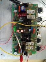
Power supply with 66000uF of Nichicon capacitance per rail, 35-0-35, 500VA toroid.
Sound is very good, powerful bass and very detailed and open mids, highs.
Here's the link to the video: DIY 120W amplifier sound test - YouTube
Cheers!!
Aniket
Hi Aniket
I think you used Sprint layout for pcb design its very good layout design. can you design your own component micros for layout design or used default micros. if you design please can you send me micros library file. my address is sanbadgujar@gmail.com.
Thanks

Hello folks,
Can someone explain the detailed steps to set bias current for this amp. I am sort of newbie and previously built rod elliott s P3a, Elvees circlophone and many chip amps. Never built amp with more than one pair of output devices. It would be great if Aniket or some one could post details steps like initial resistance in trimpot and test points etc.
Thanks in advance
Put negative lead of DVM on speaker out, test probe to junction of emitter resistor and one output transistor emitter. Set pot to maximum value. Set DVM to 2 vdc scale.
Turn amp on. TO3P package transistors like ones listed in post 1 usually can take 20-40 ma idle current. On 0.22 ohm emitter resistors in post 1 that would be 44 to 88 mv. With two pairs OT's it is best to check the other pair also, newbies may have not matched output transistors very well. You want neither transistor pair to exceed 40 ma. 100 ma is not tragic, but more risk of thermal runaway than 40.
Run amp about 1/3 power for an hour, into a dummy 8 ohm 225 W resistor for example. Then check again (silent) to make sure idle current was stable. If excessive, turn the pot down until it is under control. Note you can't read idle current with input, the out signal adds to the idle current. You can speed this test up with a hair dryer on the heat sink.
Then you can listen with speakers. Most amp designs sound the same at 20-40 ma versus 100 ma, some amps require the higher number to not have annoying crossover distortion. If you don't know what crossover distortion sounds like, turn the idle current down to zero and listen to music. If you decide on 100 ma idle current, install a fan on the heat sink. .22 ohm emitter resistors are pretty risky, I use .33 or .47 ohms myself.
Note to newbies- this design has direct coupled output transistors and can toast the voice coil of your speaker, or rip the suspension, if a solder joint pops and creates DC out. Same result if you short an output transistor with, say, a 1/4 phone plug to speaker partially pulled out creating a short. Install an aftermarket protection board between output and actual speaker. See the "protection board for only $5" for one that others found acceptable. Or buy the one from diyaudio supply up top. Or read about rjkeene protection circuits using NMOS fets. Or many others. I like the panasonic photovoltaic fet driver IC's (stocked @ digikey in US) because they come in a package with leads (DIP) for throughhole mount.
Last edited:
Put negative lead of DVM on speaker out, test probe to junction of emitter resistor and one output transistor emitter. Set pot to maximum value. Set DVM to 2 vdc scale.
Turn amp on. TO3P package transistors like ones listed in post 1 usually can take 20-40 ma idle current. On 0.22 ohm emitter resistors in post 1 that would be 44 to 88 mv. With two pairs OT's it is best to check the other pair also, newbies may have not matched output transistors very well. You want neither transistor pair to exceed 40 ma. 100 ma is not tragic, but more risk of thermal runaway than 40.
Run amp about 1/3 power for an hour, into a dummy 8 ohm 225 W resistor for example. Then check again (silent) to make sure idle current was stable. If excessive, turn the pot down until it is under control. Note you can't read idle current with input, the out signal adds to the idle current. You can speed this test up with a hair dryer on the heat sink.
Then you can listen with speakers. Most amp designs sound the same at 20-40 ma versus 100 ma, some amps require the higher number to not have annoying crossover distortion. If you don't know what crossover distortion sounds like, turn the idle current down to zero and listen to music. If you decide on 100 ma idle current, install a fan on the heat sink. .22 ohm emitter resistors are pretty risky, I use .33 or .47 ohms myself.
Note to newbies- this design has direct coupled output transistors and can toast the voice coil of your speaker, or rip the suspension, if a solder joint pops and creates DC out. Same result if you short an output transistor with, say, a 1/4 phone plug to speaker partially pulled out creating a short. Install an aftermarket protection board between output and actual speaker. See the "protection board for only $5" for one that others found acceptable. Or buy the one from diyaudio supply up top. Or read about rjkeene protection circuits using NMOS fets. Or many others. I like the panasonic photovoltaic fet driver IC's (stocked @ digikey in US) because they come in a package with leads (DIP) for throughhole mount.
Thank you very much Indianajo, very detailed explanation with additional information for newbies. Much appreciated.
Regards
Goutham
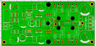
Version 2 boards, double sided 160X80mm
Hello Aniket , Nice pcb where u got that pcb. I have few silly Questions
1. Can we use 5200-1943 as Output transistor.
2. How many maximum pairs used as output transistor for more power.
3. Bias specification.
4. Any delay and protection circuit
5. PDF file or sprint layout of 2 Version double sided pcb.
Regard
Gurpreet turna
______________________________
gurpreetsingh38@outlook.com
It's singing
Amp is working on first power on.
0.2mV DC offest
51V rails.
Sounding sweet. Can't talk much about sq as tried with test speakers without any cabinet.
Thank you very much Aniket for the amp and Indianajo for very valuable guidance.
Regards
Goutham
Amp is working on first power on.
0.2mV DC offest
51V rails.
Sounding sweet. Can't talk much about sq as tried with test speakers without any cabinet.
Thank you very much Aniket for the amp and Indianajo for very valuable guidance.
Regards
Goutham
Attachments
Can this be modified with a bigger vac, for example 45-65vac?
Do you think this amplifier is better than a Honey Badger?
Or Apex AX-20?
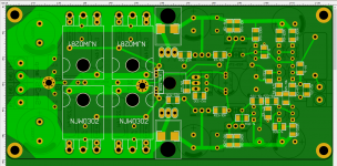
I draw a board for it in my free time...
So far, it's like this.
I will also divide the ground side: power ground, low-current and signal ones...
Or Apex AX-20?
I draw a board for it in my free time...
So far, it's like this.
I will also divide the ground side: power ground, low-current and signal ones...
Attachments
- Home
- Amplifiers
- Solid State
- Another 100W hifi amp