I need to fine-tune the power supplies for my ES9018 project.
So, let's go measure some regulators.
I'll start with the VDD supplies. This means LDOs with an output voltage of 1.2V, and a rather high output current, let's say 150mA to be safe.
Those will be powered from nearby +3.3V digital supply and decoupling capacitors, which leaves 2V of dropout, not a problem.
Power dissipation should not exceed 0.5W worst case, so SMT packages like SOT89 or SOT223 are adapted. I would rather avoid QFN or smaller if possible.
Local decoupling of this 1V2 supply will need to be strong enough to maintain a nice low impedance across the frequency range, something in the tens of mOhms should work well. A high impedance would make a noisy power supply, which can couple into nearby victims.
I will start with ceramic capacitors on the backside of the board, under the ES9018. Perhaps something bigger will be needed, maybe a POSCAP. Due to layout tightness I'd prefer to avoid big capacitors.
So, here's our LDO search criteria.
- Vin about 3.3V, Vout 1.2V, Iout 150mA
- SOT89, SOT223, or similar
- Stable with low-ESR caps at the output
- Minimize capacitor footprint
- Aim for flat and low output Z across the range
- Noise isn't really important
Some digikey search digging, I selected a few candidates.
AP7217D-12YG-13
NCP566ST12T3G
NCP694D12HT1G
NCP4687DH12T1G
RT9183-12GG
RT9166A-12GXL
TLV117112DCYT
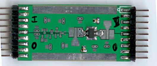
After soldering them on little test PCBs, I can mesure them.
I am using an E-MU 0202 USB soundcard. It goes to 192ksps, and the bandwidth goes up to where it should, so measurements up to 80-90 kHz are fine. The SNR on this soundcard is good below 48kHz, but when using 192ksps, the high frequencies are not so clean. Not a problem though.
The test setup is simple :
- E-Mu headphone output, through a 130R resistor and a 220µF cap, drives AC current into regulator input and output. It can drive at least +/- 15mA.
- E-Mu analog input measure regulator's input and output voltage.
Then, I had to find some software to do the impedance measurements. The requirements are simple, it has to work, obviously it has to be scriptable, and not cost an arm. I found nothing, so I just wrote the stuff in Python. The code is a bit ugly but at least it does what I want.
It does a log sine sweep and records the audio. Calibration is via the usual calibration standards (short, thru, 1 ohm resistor, etc), and then it spits out impedance, frequency response, distortion harmonics, blah blah. No problem.
Test conditions for all regulators :
- Cin : 1µF 0603 X7R // 10µF 1206 X5R ceramic capacitors at the input
- Cout : same at the output
- Vin : power supply, 2 or 3 AA batteries in series, it has a rather flat impedance of about 1 ohm up to the upper measurement range
- Rin : possibility to add a 10 ohm resistor at the input, this makes it easier to inject a signal in the input to measure PSRR
- Rout : load resistor, 15 to 68 ohms, so DC test current is 17-80 mA
So, let's go measure some regulators.
I'll start with the VDD supplies. This means LDOs with an output voltage of 1.2V, and a rather high output current, let's say 150mA to be safe.
Those will be powered from nearby +3.3V digital supply and decoupling capacitors, which leaves 2V of dropout, not a problem.
Power dissipation should not exceed 0.5W worst case, so SMT packages like SOT89 or SOT223 are adapted. I would rather avoid QFN or smaller if possible.
Local decoupling of this 1V2 supply will need to be strong enough to maintain a nice low impedance across the frequency range, something in the tens of mOhms should work well. A high impedance would make a noisy power supply, which can couple into nearby victims.
I will start with ceramic capacitors on the backside of the board, under the ES9018. Perhaps something bigger will be needed, maybe a POSCAP. Due to layout tightness I'd prefer to avoid big capacitors.
So, here's our LDO search criteria.
- Vin about 3.3V, Vout 1.2V, Iout 150mA
- SOT89, SOT223, or similar
- Stable with low-ESR caps at the output
- Minimize capacitor footprint
- Aim for flat and low output Z across the range
- Noise isn't really important
Some digikey search digging, I selected a few candidates.
AP7217D-12YG-13
NCP566ST12T3G
NCP694D12HT1G
NCP4687DH12T1G
RT9183-12GG
RT9166A-12GXL
TLV117112DCYT
After soldering them on little test PCBs, I can mesure them.
I am using an E-MU 0202 USB soundcard. It goes to 192ksps, and the bandwidth goes up to where it should, so measurements up to 80-90 kHz are fine. The SNR on this soundcard is good below 48kHz, but when using 192ksps, the high frequencies are not so clean. Not a problem though.
The test setup is simple :
- E-Mu headphone output, through a 130R resistor and a 220µF cap, drives AC current into regulator input and output. It can drive at least +/- 15mA.
- E-Mu analog input measure regulator's input and output voltage.
Then, I had to find some software to do the impedance measurements. The requirements are simple, it has to work, obviously it has to be scriptable, and not cost an arm. I found nothing, so I just wrote the stuff in Python. The code is a bit ugly but at least it does what I want.
It does a log sine sweep and records the audio. Calibration is via the usual calibration standards (short, thru, 1 ohm resistor, etc), and then it spits out impedance, frequency response, distortion harmonics, blah blah. No problem.
Test conditions for all regulators :
- Cin : 1µF 0603 X7R // 10µF 1206 X5R ceramic capacitors at the input
- Cout : same at the output
- Vin : power supply, 2 or 3 AA batteries in series, it has a rather flat impedance of about 1 ohm up to the upper measurement range
- Rin : possibility to add a 10 ohm resistor at the input, this makes it easier to inject a signal in the input to measure PSRR
- Rout : load resistor, 15 to 68 ohms, so DC test current is 17-80 mA
Attachments

First victim : LM317
I will show the same curves for all tested regulators.
Here, impedance is plotted :
- with/without 10R resistor in the supply (different color)
- for all values of load resistors (all curves of the same color).
Its dropout is a bit high, and when Rin is set to 10 ohms, lowering input voltage at the higher test current, it stops working, as shown by the uppermost blue curve.
Also, this old fart was born before the age of ceramic decoupling capacitors. It does not like modern caps with low ESR. Here, it oscillates nicely, as shown by the huge impedance peak.
It will be unstable with virtually all modern capacitors, btw. I just tested it because I had one around. Using LM317 means the caps have to be selected appropriately, as per datasheet, with high enough ESR to make it stable, and bypass caps have to be applied with caution.
So, LM317 is out.
Attachments
Next victim : P-type LDOs
The typical LDO has an internal architecture like this :
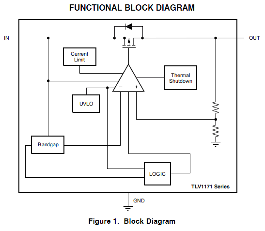
To achieve low dropout, the pass element must be either a PMOS or a PNP transistor, which acts more or less as a current source, driven by the error amplifier.
Extremely low dropouts can be achieved (in the 10s of mV for some LDOs). PMOS also allow extremely low ground currents.
However, the output, being a drain or a collector, is high impedance before feedback is applied. The output impedance therefore depends entirely on feedback.
This means we can expect it to rise at high frequencies... but how much ?
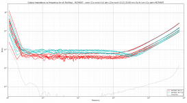
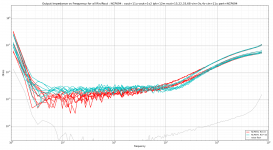
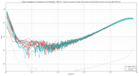
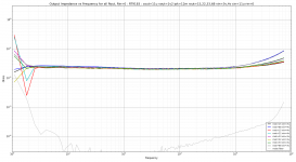
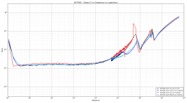
Here are 4 different LDOs measured, same as above, at various input voltages and load currents.
Some of them have impedance varying with input voltage and load, others not, but all have the same characteristic : impedance is very low at LF but starts to rises at not so high frequencies.
At 100 kHz all of them don't look so good.
The AP7217 impedance rises enough to show the 10µF output cap taking over at about 60 kHz.
The typical LDO has an internal architecture like this :
To achieve low dropout, the pass element must be either a PMOS or a PNP transistor, which acts more or less as a current source, driven by the error amplifier.
Extremely low dropouts can be achieved (in the 10s of mV for some LDOs). PMOS also allow extremely low ground currents.
However, the output, being a drain or a collector, is high impedance before feedback is applied. The output impedance therefore depends entirely on feedback.
This means we can expect it to rise at high frequencies... but how much ?
Here are 4 different LDOs measured, same as above, at various input voltages and load currents.
Some of them have impedance varying with input voltage and load, others not, but all have the same characteristic : impedance is very low at LF but starts to rises at not so high frequencies.
At 100 kHz all of them don't look so good.
The AP7217 impedance rises enough to show the 10µF output cap taking over at about 60 kHz.
Attachments
-
 P-LDO-diagram.png8.8 KB · Views: 1,291
 -
 Output Impedance vs Frequency for all Rin-Rout - TLV1171.png320.6 KB · Views: 170
 -
 Output Impedance vs Frequency for all Rin-Rout - NCP4687.png307.1 KB · Views: 153
 -
 Output Impedance vs Frequency for all Rin-Rout - NCP694.png338.2 KB · Views: 183
 -
 Output Impedance vs Frequency for all Rin-Rout - AP7217.png347.2 KB · Views: 193
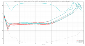
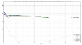
However, not all PMOS LDOs are slow.
Those two by Richtek have a bit higher dropout that the others, therefore I do not show the curves with 10R resistor in the power supply, which reduces the input voltage too much. They're perfectly happy at 3V input, so no problem.
Their impedance is just flat. At low frequencies, it is higher than the previous bunch, but at high frequencies, those two start to win.
Especially interesting is the second one which is ruler flat at 30-40 mOhm from DC to 80 kHz. Nice.
EDIT: fireworks: I added the forgotten pics !...
Attachments
Last edited:
However, not all PMOS LDOs are slow.
Those two by Richtek have a bit higher dropout that the others, therefore I do not show the curves with 10R resistor in the power supply, which reduces the input voltage too much. They're perfectly happy at 3V input, so no problem.
Their impedance is just flat. At low frequencies, it is higher than the previous bunch, but at high frequencies, those two start to win.
Especially interesting is the second one which is ruler flat at 30-40 mOhm from DC to 80 kHz. Nice.
Can you post the graphs for those two also ?
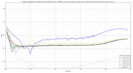
And finally, we have an outsider, NCP566.
What is inside isn't known, the datasheet mentions that it has an "output stage". Well, yeah. The usual graph of Dropout voltage versus current is missing. There must be something super secret in there...
This one seems to require a minimum load current. The soundcard volume is set to +/- 12mA peak, and the 68R load resistor draws 17.6mA... in this case the regulator switches in and out of some sort of powersaving mode, or just switches on and off (its output is distorted).
The 33 ohms resistor makes it happy. It could probably work with less.
Anyway, once this minimum current is satisfied, the performance is just incredible. 3 mOhm at 10kHz, 6 mOhms at 70 kHz, I had to check if the output was short circuited, but it isn't...
The datasheet just understates "The fast loop response and low dropout voltage make this regulator ideal for applications where low voltage and good
load transient response are important." and "Ultra Fast Transient Response (1.0 µs)"
But all other datasheets have words like "ultra fast"... this one has impressive datasheet transient response plots though.
It has low noise, too.
To be continued...
Attachments
That could explain the excellent performance !
I have added :
- 470uF Panasonic LF ultra-low-ESR polymer capacitor at the output
- large 2700uF Nichicon PW low-impedance electrolytic at the niput
The LF's are really nice caps. I have used some at the output of a switching regulator, a tiny 220uF cap eats 2 amps of ripple, doesn't heat at all, it doesn't care, and the output is pretty clean.
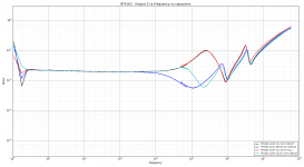
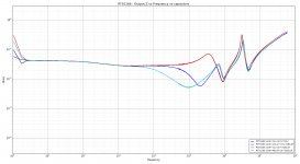
Anyway. More curves.
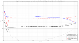
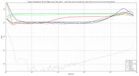
The dashed lines are previous measurements, with only ceramic caps. The full lines are measurements with capacitors. Same color, same regulator.
Left plot : the slow ones. Here we got some problems. Three are definitely unstable. The TLV1171 looks ok, except, well, it would need an enormous capacitor to have a flat impedance curve.
So, I will no longer consider these regulators.
Right plot : the fast ones. Very different picture...
- The two Richtek regs deliver a smooth transition from regulator to capacitor between 10-20kHz.
- The NCP566 desn't seem to care.
Those three are quite spectacular...
I have added :
- 470uF Panasonic LF ultra-low-ESR polymer capacitor at the output
- large 2700uF Nichicon PW low-impedance electrolytic at the niput
The LF's are really nice caps. I have used some at the output of a switching regulator, a tiny 220uF cap eats 2 amps of ripple, doesn't heat at all, it doesn't care, and the output is pretty clean.
Anyway. More curves.
The dashed lines are previous measurements, with only ceramic caps. The full lines are measurements with capacitors. Same color, same regulator.
Left plot : the slow ones. Here we got some problems. Three are definitely unstable. The TLV1171 looks ok, except, well, it would need an enormous capacitor to have a flat impedance curve.
So, I will no longer consider these regulators.
Right plot : the fast ones. Very different picture...
- The two Richtek regs deliver a smooth transition from regulator to capacitor between 10-20kHz.
- The NCP566 desn't seem to care.
Those three are quite spectacular...
Attachments
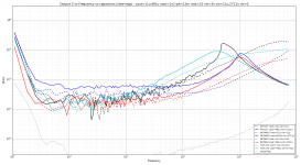
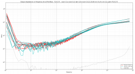
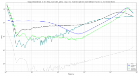
Stitching together the soundcard and network analyzer data provides a whooping frequency range of 5 Hz to 60 MHz.
Of course, above a few MHz, a test with a real layout and appropriate ceramic capacitors would be needed, so please don't look too much to the right.
Here, for each of the 3 winninig regulators, 4 tests are performed.
Black trace :
Cin = 1µ X75 // 10µ X5R // 2700µ low-ESR
Cout = 1µ X75 // 10µ X5R
Red trace :
Cin = same Cin as Black, plus 470µF LF polymer
Cout = 1µ X75 // 10µ X5R
The two Ricktek regs show no difference between those two. Thus, the ceramics at the input are sufficient.
For the NCP566, the adding a local polymer cap at the input seems to cause some problems. I would have liked to look at the waveforms, but my scope died... However, with more output decoupling, the problems disappear.
With only ceramic caps, its output impedance is still very low, 10mOhms at 200kHz, impressive !
Blue trace :
Cin = same Cin as Red
Cout = 1µ X75 // 10µ X5R // 100µ Nichicon R7 polymer
Cyan trace :
Cin = same Cin as Red
Cout = 1µ X75 // 10µ X5R // 470µ Panasonic LF polymer
Blue/Cyan comparison :
Here the difference is the output capacitor, 100µ versus 470µ. Both are high performance polymer caps, with ridiculously low ESR and excellent HF performance.
NCP566 seems to like the 470u cap better. It provides a smooth transition from regulator to capacitor, whereas the 100µ cap creates a small peak.
This is due to the output impedance of the regulator becoming inductive at HF. It behaves like an inductor having an extremely low ESR (1-2 mOhms). So, in parallel with a cap, it can resonate depending on the value and the ESR/ESL of the cap. The same thing happens when parallelling capacitors. 470µF seems to be the sweet spot.
For the two richteks, no such problem, since their output impedance is higher, they behave like an inductor with more ESR, which dampens the resonance. The caps lower the impedance above 10-100kHz.
Capacitor choices :
For the NCP566 I would stay with the 470u LF cap which provides a nice transition. However its ESR is extremely low, which means it creates a not so good looking antiresonance peak with the 10µ ceramic. This means more low-ESR caps would be needed to fill the holes, maybe around 50-100µF, or more large ceramics. More tests needed.
The Richtek regs would be better associated with a capacitor having higher ESR, perhaps 15-20 mOhms, instead of the 4-7 mOhms of the LF/R7. This would flatten the impedance curve and soften the antiresonance peak with the ceramic caps. Thus, less capacitors would be needed in total.
So, these regs offer two design options.
The NCP design target could be :
- 2mOhms up to 10k
- < 5 mOhms up to 100k
- < 10 mOhms up to HF
This option would use many capacitors.
The Richtek design target could be :
- flat 20 mOhms up to HF
This option would use less capacitors than the NCP.
Decisions, decisions...
Attachments
The transient response from the datasheet looks nice. I'll add it to my list.
Meanwhile I measured some caps using the network analyzer.
Same data in alphabetical order.
Thru hole caps were soldered at the edge of a 0.2mm thick plate with copper on both sides (signal and ground). I did another test fixture with less inductance (much more annoying to use) and the difference is about 400pH... Results should be OK.
SMD caps are measured properly (fixture is a transmission line).
So, for thru holes, as expected the ESL is mostly correlated with the spacing between the capacitor pins, which determines loop area.
The fim caps performed just like electrolytics of the same size. For example the 1u 63V MKT Yellow "box" capacitor would be absolutely useless for bypassing anything except very large capacitors, and in that case, a small high performance aluminium cap will perform better.
The "LCC 1.5u 250V MKT axial" is a rather large axial leaded "roll" type MKT capacitor, like some boutique audiophile vendors provide. It was wired like some "tweaks" that sometimes show up here, ie, with long leads. Needless to say its performance as decoupling cap would be absolute rock bottom.
Meanwhile I measured some caps using the network analyzer.
Code:
                                           Pin Spacing  ESR mOhm   ESL nH
10u 1206 X7R                                             5.8         1.1
Panasonic SPCAP CD 100u 4V 18mOhm SMD 7x4mm EEF         19.1         1.6
Sanyo OSCON SC 10u 10V e2.54 d5.5 h7             2.54   27.4         2.9
Sanyo OSCON SC 22u 16V e2.54 d6.5 h10            2.54   17.1         3.2
Rubycon ZL 33u 63V e2.54 d6 h11                  2.54   97.9         3.5
Panasonic LF 470u 6.3v e3.5 d8 h11 LowL Mount     3.5    6.0         3.9
Rubycon ZL 100u 25V e2.54 d6 h11                 2.54   72.6         4.1
Panasonic LF 470u 6.3v e3.5 d8 h11                3.5    6.6         4.3
Nichicon R7 100u 10v e3.5 d8 h11                  3.5    7.2         4.6
Panasonic FM 220u 35V e3.5 d8 h16                 3.5   27.9         5.5
NoName 100u 16V e3.5 d8 h11                       3.5  214.4         5.5
Rubycon BlackGate F 100u 25V e5.08 d10 h21       5.08   49.3         5.9
Noname 1u 63V MKT Yellowbox e5.08 d5.8x7.5 h10   5.08   15.8         5.9
Panasonic LF 470u16v e5.08 d10 h13               5.08    6.7         6.2
Elna Starget 470u 16V e5.08 d10 h20              5.08   77.7         6.6
Rubycon ZL 470u 16V e5.08 d10 h13                5.08   29.7         6.7
Sanyo OSCON SVP 1200u 4V d10 h12                    7   10.6         6.7
Nichicon PW 2700u 35V e8 d18 h31                    8   17.7        10.9
Philips MKT 2u2 250V e22 d9.5x25 h18               22   18.7        17.6
LCC 1.5u 250V MKT axial hi-L mount e42             40    9.9        57.5
Same data in alphabetical order.
Code:
                   Capacitor            Pin Spacing ESR mOhm    ESL nH
10u 1206 X7R                                           5.8         1.1
Elna Starget 470u 16V e5.08 d10 h20            5.08   77.7         6.6
LCC 1.5u 250V MKT axial hi-L mount e42           40    9.9        57.5
Nichicon PW 2700u 35V e8 d18 h31                  8   17.7        10.9
Nichicon R7 100u 10v e3.5 d8 h11                3.5    7.2         4.6
NoName 100u 16V e3.5 d8 h11                     3.5  214.4         5.5
Noname 1u 63V MKT Yellowbox e5.08 d5.8x7.5 h10 5.08   15.8         5.9
Panasonic FM 220u 35V e3.5 d8 h16               3.5   27.9         5.5
Panasonic LF 470u 6.3v e3.5 d8 h11              3.5    6.6         4.3
Panasonic LF 470u 6.3v e3.5 d8 h11 LowL Mount   3.5    6.0         3.9
Panasonic LF 470u16v e5.08 d10 h13             5.08    6.7         6.2
Panasonic SPCAP CD 100u 4V 18mOhm SMD 7x4mm           19.1         1.6
Philips MKT 2u2 250V e22 d9.5x25 h18             22   18.7        17.6
Rubycon BlackGate F 100u 25V e5.08 d10 h21     5.08   49.3         5.9
Rubycon ZL 100u 25V e2.54 d6 h11               2.54   72.6         4.1
Rubycon ZL 33u 63V e2.54 d6 h11                2.54   97.9         3.5
Rubycon ZL 470u 16V e5.08 d10 h13              5.08   29.7         6.7
Sanyo OSCON SC 10u 10V e2.54 d5.5 h7           2.54   27.4         2.9
Sanyo OSCON SC 22u 16V e2.54 d6.5 h10          2.54   17.1         3.2
Sanyo OSCON SVP 1200u 4V d10 h12                  7   10.6         6.7
Thru hole caps were soldered at the edge of a 0.2mm thick plate with copper on both sides (signal and ground). I did another test fixture with less inductance (much more annoying to use) and the difference is about 400pH... Results should be OK.
SMD caps are measured properly (fixture is a transmission line).
So, for thru holes, as expected the ESL is mostly correlated with the spacing between the capacitor pins, which determines loop area.
The fim caps performed just like electrolytics of the same size. For example the 1u 63V MKT Yellow "box" capacitor would be absolutely useless for bypassing anything except very large capacitors, and in that case, a small high performance aluminium cap will perform better.
The "LCC 1.5u 250V MKT axial" is a rather large axial leaded "roll" type MKT capacitor, like some boutique audiophile vendors provide. It was wired like some "tweaks" that sometimes show up here, ie, with long leads. Needless to say its performance as decoupling cap would be absolute rock bottom.
Great.
you mean Panasonic FL series capacitor?
Two years ago I bought them for motherboard recap purpose. After they arrived, they looks like fakes. But after measuring ESR, i was speechless, all of them measured between 5 - 7 mOhm. Crazy cap
470uF Panasonic LF ultra-low-ESR polymer capacitor
you mean Panasonic FL series capacitor?
Two years ago I bought them for motherboard recap purpose. After they arrived, they looks like fakes. But after measuring ESR, i was speechless, all of them measured between 5 - 7 mOhm. Crazy cap
D'oh. It was Nichicon LF.
I have simulated various capacitor mixes, trying to reduce the antiresonance peak at the transition between bulk and ceramic capacitors, but it is not easy...
And I found those : they spec 2nH inductance which makes it a lot smoother...
http://www.nichicon.co.jp/english/products/pdf/2013fpcap_catalog_s8.pdf
Yep, sorry about that. And since I can't edit my posts, readers (if any) should replace "panasonic LF" with "nichicon LF"
Nice caps but the measurements show the very low ESR ones all have a bit too much ESL, which doesn't help the transition to ceramics. They would either need too much ceramic, a chip polymer tantalum to fill the hole, or more ESR to suppress the resonance.
Anyway, the 1v2 regulator is chosen, it will be among the 3 winners, either NCP566 or the Rickteks.
I put a NCP565 on my digikey list just in case, along with some polymer caps with a bit more ESR and a bit less ESL.
So, that's it for now regarding these 1v2 regulators... what to do now ? Test 3v3 regulators of course...
Attachments
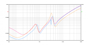
First plot, the flat ones...
No ultra low output impedance here ! The best are around 0.1 ohm.
Based on output impedance alone, the 4x price difference between the most expensive and the cheapest of the bunch.
Second plot, the wavy ones...
LT1761 delivers a funny-looking impedance graph (LTSpice agrees). It is by far the most expensive of the bunch and doesn't seem to provide any advantage, unless having low impedance only around 800 Hz could be useful ?.... I included it because people seem to like it...
Richtek RT9193 scores on output impedance (again), although the noise on this one is 100µV so not "ultra-low" as the datasheet claims, also it is not as fast as its 1v2 brothers RT9183 and RT9166... which exist in 3v3 versions (very difficult to find though).
Of course, noise is important too, but on a regulator with 10µV output noise and 0.1ohm output impedance, a 1mA variation of load current is enough to make the output voltage vary 10x the specified noise. So, the low-noise ones (ADP151) would be nice to power something which draws a constant current, like a clock.
So, no real winner this time... For the ES9018, DVCCT isn't critical, but DVCCB seems to be important for jitter, so I'll have to measure the current to check if it is constant or not.
I will also do a comparison with a TL431.
And, before I forget...
Noise measured with scope at 100ms/div, ie low end of frequency at about 1 Hz, using Groner's preamp :
Not that important for a core voltage regulator, but the AP7217 certainly does its best...
"Board flex" is the voltage deviation when I press on the board with my finger. No problems here.
Noise measured with scope at 100ms/div, ie low end of frequency at about 1 Hz, using Groner's preamp :
Code:
Reg     Cout    uVpp noise  uVRMS noise     uV board flex
RT9183	480u	450	        146	            50
TLV1117	10u	    461	        148	            0
NCP4687	10u	    630	        215	            150
NCP694	10u	    630	        220	            100
RT9166	480u	650	        220	            0
NCP566	480u	656	        240	            50
AP7217	10u	    3300	    1140	        500
Not that important for a core voltage regulator, but the AP7217 certainly does its best...
"Board flex" is the voltage deviation when I press on the board with my finger. No problems here.
My experience with the PCM1792 indicates that it draws pretty much constant current from both its analogue and digital supplies, with a small change in the analogue draw as one increases the drive level beyond the quiescent conditions and even then the change is quite small.
These measurements were only performed with a DMM mind you, so would only show an average current draw vs any transient demands in the digital domain.
These measurements were only performed with a DMM mind you, so would only show an average current draw vs any transient demands in the digital domain.
I'll keep you posted on the measurements I'll do on ES9018.
In the meantime I have measured a few samples of good old TL431.
Here is the noise with scope on 100ms/div setting and Groner's x1000 preamp.
This corresponds roughly to the noise in the preamp's bandwidth, which is specified at 10 Hz-100kHz +/- 0.1dB (so the 3dB points are wider, of course).
I should do a FFT... when I find a way to import the scope captures into the PC...
As we can see it is important to pick the right one... TL431 also has high frequency noise, the capacitor filters it out.
The output impedance is desperately high at about 0.1 ohm (see datasheet).
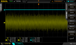
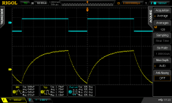
Attached are two scope shots of OnSemi TL431 :
- Noise (using x1000 preamp)
- Transient response. The shunt current is stepped between 23mA and 40mA, a 17mA step. The impedance of the device is specified at 0.1 ohm, accordingly this produces about 1.75mV peak-peak voltage variation.
In the meantime I have measured a few samples of good old TL431.
Here is the noise with scope on 100ms/div setting and Groner's x1000 preamp.
This corresponds roughly to the noise in the preamp's bandwidth, which is specified at 10 Hz-100kHz +/- 0.1dB (so the 3dB points are wider, of course).
I should do a FFT... when I find a way to import the scope captures into the PC...
Code:
			C=0		C=470µF LF
NCP431 (ON)		2000 µV		not measured
AP431 (Diodes)		1200 µV		not measured
TL431 (OnSemi)		680 µV		33 µV
TL431 (NXP)		650 µV		28 µV
LM431 (Fairchild)	470 µV		28 µV
Short circuit		5 µV
As we can see it is important to pick the right one... TL431 also has high frequency noise, the capacitor filters it out.
The output impedance is desperately high at about 0.1 ohm (see datasheet).
Attached are two scope shots of OnSemi TL431 :
- Noise (using x1000 preamp)
- Transient response. The shunt current is stepped between 23mA and 40mA, a 17mA step. The impedance of the device is specified at 0.1 ohm, accordingly this produces about 1.75mV peak-peak voltage variation.
Attachments
- Status
- This old topic is closed. If you want to reopen this topic, contact a moderator using the "Report Post" button.
- Home
- Amplifiers
- Solid State
- Experimentations on Regulators