Q9, 59 must be MJ15024
Q8, 60 must be MJ15025
You should add a pre-driver, making the output stage a triple. Use the MJE15034 and MJE15035.
I would add a 2.7K in series with the base of Q2 and move the 100pF to the base of same and change to 390pF, this forms a pole at about 125Khz.
Q4 and Q5 should run no more than about 10mA, so R11 and R12 should be more like 390Ω. With 4.3mA though each the voltage drop across 390Ω will be 1.68V, which will make the current in Q4 and Q5 about 10mA.
The amplifier might put out 5KW at 1Ω for a bit before it blows up. The SOA on the outputs is 100W at 100V. Run another supply tier and you could make it work properly in class G or H, or run the other tier from a tracking down-converter like a Sunfire or Bash amplifier.
I'm sure there will be more details, but this is all the time I have for now.
Last edited:
Greeting Mr. Workhorse,
This is just a theortical design,I also know that if I make a 20kw per channel and even if I use 15024-25 I will need minimum 2000 of them,in class AB, practically not possible,Just wanted that if seniors like you can check the circuit to make an amp of 4 to 5 kw per channel will be a great help for me
This is just a theortical design,I also know that if I make a 20kw per channel and even if I use 15024-25 I will need minimum 2000 of them,in class AB, practically not possible,Just wanted that if seniors like you can check the circuit to make an amp of 4 to 5 kw per channel will be a great help for me
Anyone checked http://sound.westhost.com/project117.htm
Last edited by a moderator:
1.5Kw Amp.

Regards.
Yes, I've made it and with some minor modifications it will work, but not as per schematic, specially on the bias circuitry, you can modify it to get more power also, but that's pointless because there's already a very good amount of power.Anyone checked http://sound.westhost.com/project117.htm
Regards.
Last edited:
 pulled some posts, guys let us stick to technical discussions please....
I would suggest lowering the ±V by a factor of 0.707, this will be much safer, and require only about one-fourth the number of outputs (and half the number of drivers) due to SOA parameters of the devices used.
The reduction in power will only be 3dB.
I put together such an amplifier 20 years ago with only 10 pair of MJ15024/25 running 1Ω and it is still running fine today. It's probably about time to replace all the electrolytics though, I should contact the owner.
The reduction in power will only be 3dB.
I put together such an amplifier 20 years ago with only 10 pair of MJ15024/25 running 1Ω and it is still running fine today. It's probably about time to replace all the electrolytics though, I should contact the owner.
Last edited:
I would suggest lower than that to start off with. Maybe +/-45, +/-90 and +/-135V taps on the trafo. If you're doing a custom wind job anyway why not put the extra taps so you can convert to a multi-tier supply eventually? Something this big needs it to really be practical, and can operate class AB off the lower tier (or two) while the project is being developed.
I've run +/-127V in pure class AB, but the output stage was cascode (S-Leach type) with 5 parallel/2 series. The only part of it that ever burned up was the extension cord. It blows hot air like a hair dryer, and a 15 amp breaker won't stay in the 'on' position. Even 20 amp will nuisance-trip occasionally. All of my subsequent designs were class H - even the little 100 watter. I hope you have a dedicated 30A circuit just for testing.
To all the naysayers who say that "it won't put out anywhere near that much" need to take a close look at those toroids! Looks like about an 8kVA.
3kW into 2 ohms is a real possibility. 55 amps won't be a problem for that many output trannies or that big a toroid. Reliability is another issue - as it was with the original PL700. That's a design issue the can be addressed.... eventually. Workhorse's first iterations probably didn't work either.
obsession for power
when i was younger i also dreamed of building the biggest and the mightiest amp......i am still dreaming.....
yes, you can build a 5kw amp out of that 8kva torroid...but then you will learn that there are amps out there more powerful that your 5kw amp, so where does that leave you?
classAB up to about 300watt is very practical imho....above that, classD, G, or H is available....
so then it becomes just a matter of adding more amps, more speakers to your system if more power is desired......
why put all your eggs in one basket? if the basket crashes, you lose all your eggs in one go.....
True enough.
In the early 80's I designed and built a PA system for the Moscow Circus (the real, Soviet era one) .
They did NOT want a couple "big" amps.
On their spec, I built a ton of long *narrow* sound columns , each housing 8 6"x9" car type speakers mounted edge to edge , the columns were just 8" wide, because they were hung all around the huge stage and had to block vision the least possible, each block of 4 was powered by a dedicated rack of 6 100W amps , meaning 2 backups per rack.
Each rack had a patchbay so a dead one could be replaced in seconds, and all modules were plug-in , so they could be pulled for repair elsewhere, with the rack still working nonstop.
The reason behind that: Moscow Circus, when on tour, has *continuous" shows 1PM to 1 AM , every day of the week.
No time for "regular" maintenance, so the answer is a lot of redundance built-in.
If any 100W amp or column failed during the show, since they were 4 or 5 meters away , no "deaf" spots would be noticed, at most a somewhat lower SPL at some seats.
I think they approached problems with a "military" mindset.
And of course, a dead 1KW amp during a show would have been a disaster.
Thank you Mr. Tony and Mr. Fahey.
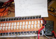
For you Information let me tell you I have already practically made class AB amps up to real nondistorted power of 1400 watts per channel in to 2 ohm, see the photo attached, I have tested it in field for 6 hours with 8 speakers 15" direct and has passed the test.8/8 the load was 1 ohm, the meter in picture showing peak voltage on 2 ohm.with speakers in field it was 44 volts and 29 amperes.
For you Information let me tell you I have already practically made class AB amps up to real nondistorted power of 1400 watts per channel in to 2 ohm, see the photo attached, I have tested it in field for 6 hours with 8 speakers 15" direct and has passed the test.8/8 the load was 1 ohm, the meter in picture showing peak voltage on 2 ohm.with speakers in field it was 44 volts and 29 amperes.
- Status
- This old topic is closed. If you want to reopen this topic, contact a moderator using the "Report Post" button.
- Home
- Amplifiers
- Solid State
- Has any one built this 1KW amp?