Hello Tony,
I've Entered All Information For Those Who Encounter Interest In Such Components,
I've Just Found This Site By Accident, I'll Try To Make Contact, As They Offer Email Address And Other Contact Information.
Just Post The Information Because Sounds Very Good To Start A DIY Project With Such Hi-Power Components....
Cheers...")
hi, were you able to make contact? maybe they would like to give samples to vedmitraa so that he can try out in his amps.....
vedmitraa,
you may want to use single cotton covered magnet wires if such is available to you, simplifies insulation imho....cotton tapes over your primary coils is good....
WTH!!!!
Just Wondering What Kind Of Protections Can Withstand Such Amplifier, Which Will Be The Bias Current Set-Up At Idle, Amount Of Capacitance On PSU And Current Demand On Wall's Socket At Full Power...contactor
and a soft start circuit.
Here's The Phone Number Once Again...
Fax: +44(0)1455 552612
Email: sales@semelab-tt.comLeicestershire LE17 4JB, UK.Email: sales@magnatec-tt.com. Website: www.magnatec-tt.com
OnSemi Can And Will Provide Samples Of MJL4281A/4302A/MJE15034/35 They Are A Very Good High Power Devices....
Best Regards....
Tel: +44(0)1455 552505hi, were you able to make contact? maybe they would like to give samples to vedmitraa so that he can try out in his amps.....
vedmitraa,
you may want to use single cotton covered magnet wires if such is available to you, simplifies insulation imho....cotton tapes over your primary coils is good....
Fax: +44(0)1455 552612
Email: sales@semelab-tt.comLeicestershire LE17 4JB, UK.Email: sales@magnatec-tt.com. Website: www.magnatec-tt.com
OnSemi Can And Will Provide Samples Of MJL4281A/4302A/MJE15034/35 They Are A Very Good High Power Devices....
Best Regards....
Is that a question or a statement?Just Wondering What Kind Of Protections Can Withstand Such Amplifier, Which Will Be The Bias Current Set-Up At Idle, Amount Of Capacitance On PSU And Current Demand On Wall's Socket At Full Power.
Just Asking...
No Matter If I Have A Very Close Idea About The Answer Tough, There's Some Constructing & Testing Procedures That Requires Special Care Like Well Designed VAS Circuit, Properly Biased Main Output Transistors, Proper Heat Tracking Method As Well As Proper Cooling Of Output Stage, Not To Mention To Observe The SOA Of Transistors Elected For The Task Very Carefully, Plenty Output Transistors Doesn't Necessary Mean Lots Of Power As There Are More Things To Take Into Consideration, Better Go With Class "H" For This Kind Of Power, But This Is Just My Point Of View...
Cheers...
If I'm Wondering, It Should Be A BIG Question,Is that a question or a statement?
No Matter If I Have A Very Close Idea About The Answer Tough, There's Some Constructing & Testing Procedures That Requires Special Care Like Well Designed VAS Circuit, Properly Biased Main Output Transistors, Proper Heat Tracking Method As Well As Proper Cooling Of Output Stage, Not To Mention To Observe The SOA Of Transistors Elected For The Task Very Carefully, Plenty Output Transistors Doesn't Necessary Mean Lots Of Power As There Are More Things To Take Into Consideration, Better Go With Class "H" For This Kind Of Power, But This Is Just My Point Of View...
Cheers...
Last edited:
If I'm Wondering, It Should Be A BIG Question,
No Matter If I Have A Very Close Idea About The Answer Tough, There's Some Constructing & Testing Procedures That Requires Special Care Like Well Designed VAS Circuit, Properly Biased Main Output Transistors, Proper Heat Tracking Method As Well As Proper Cooling Of Output Stage, Not To Mention To Observe The SOA Of Transistors Elected For The Task Very Carefully, Plenty Output Transistors Doesn't Necessary Mean Lots Of Power As There Are More Things To Take Into Consideration, Better Go With Class "H" For This Kind Of Power, But This Is Just My Point Of View...
Cheers...
BIG an understatement, HUMONGOUS is more appropriate....
if he is not doing sine wave testing and will just make music, he can probably get away with the toroid that he has.....
Rod Elliot came up with a design here...Project 117
despite the warnings about
people still take it seriously....One flash and you're ash !
Project 117 Certainly A Very Powerful Amp But....
Very Good To Try, And Somewhat Expensive Believe Me....
Cheers...
Yeah, That's The Right Word, And For Rod's Design Let Me Tell You, It Works, And It's Very Powerful Indeed, I've Built The Project 117 And States 1500W @4 Ohm, Believe Me, This Design Worth The Effort, As Long As You Make Some Arrangements In The Bias Circuitry, The Circuit As Per Schematic Will Not Work Just Because Of That Detail, If You Apply Power Following Schematic You'll Certainly Blow Up The Output Stage Transistors, Once You Resolve The Little Puzzle And Get 150mv Across Driver's Emitter Resistor It Will Perform Powerful, Stable And Reliable With Lots Of Headroom, As Stated, With +-130VDC, +-135VDC Rails, And I Didn't Use Mj15024/25, But MJL4281A/4302A, 14 Devices Per Rail Including Drivers, Massive 2Kva Xformer, Decent Capacitance Rating 12-10,000uf -160V-Large-Can-Type Caps And BIG Fan Cooled Heatsink.BIG an understatement, HUMONGOUS is more appropriate....
if he is not doing sine wave testing and will just make music, he can probably get away with the toroid that he has.....
Rod Elliot came up with a design here...Project 117
despite the warnings about people still take it seriously....
Very Good To Try, And Somewhat Expensive Believe Me....
Cheers...
Last edited:

Yeah, That's The Right Word, And For Rod's Design Let Me Tell You, It Works, And It's Very Powerful Indeed, I've Built The Project 117 And States 1500W @4 Ohm, Believe Me, This Design Worth The Effort, As Long As You Make Some Arrangements In The Bias Circuitry, The Circuit As Per Schematic Will Not Work Just Because Of That Detail, If You Apply Power Following Schematic You'll Certainly Blow Up The Output Stage Transistors, Once You Resolve The Little Puzzle And Get 150mv Across Driver's Emitter Resistor It Will Perform Powerful, Stable And Reliable With Lots Of Headroom, As Stated, With +-130VDC, +-135VDC Rails, And I Didn't Use Mj15024/25, But MJL4281A/4302A, 14 Devices Per Rail Including Drivers, Massive 2Kva Xformer, Decent Capacitance Rating 12-10,000uf -160V-Large-Can-Type Caps And BIG Fan Cooled Heatsink.
Very Good To Try, And Somewhat Expensive Believe Me....
Cheers...
if ever i will do Project 117, i will do a lot of mods.....along the likes of a leach amp....
Lol !!!
Best Regards,
The Craziest......lol.....
Actually You Really Do Not Need Lots Of Mods, Just Correction Of The Bias Circuitry And You're Done, As This Is A Real-World Working Design Proven By Myself And Not Just Simulated-Working Design, As Well As Kanwar's Old Quasi Design, I've Made Both And BOTH Need Mods To Get Them Work In A Reliable And Stable Way, No Issues Since Those Mods Were Made To Both Designs, Even When Pushed Hard, Rod's Design Sonics Are Very Good Either For Subs Or Tops, No Strange Audible Artefacts In The 20-20Khz Spectrum But Beware Of Output Power Vs Your Load, This Is A Truly Very Respectable Power Amplifier WORKING Design, And Believe Me, Is Waaay Better To Plug It To A 220V, Instead Of A 110V Mains....Needless To Explain Why....if ever i will do Project 117, i will do a lot of mods.....along the likes of a leach amp....
Best Regards,
The Craziest......lol.....
One More.....
Take Into Consideration Mr Andrew Lebon Alsothat makes three of us.....any one else? please raise your hands...
Thanks a lot Mr. Kimberlator and Mr. Tony ,
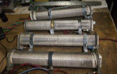
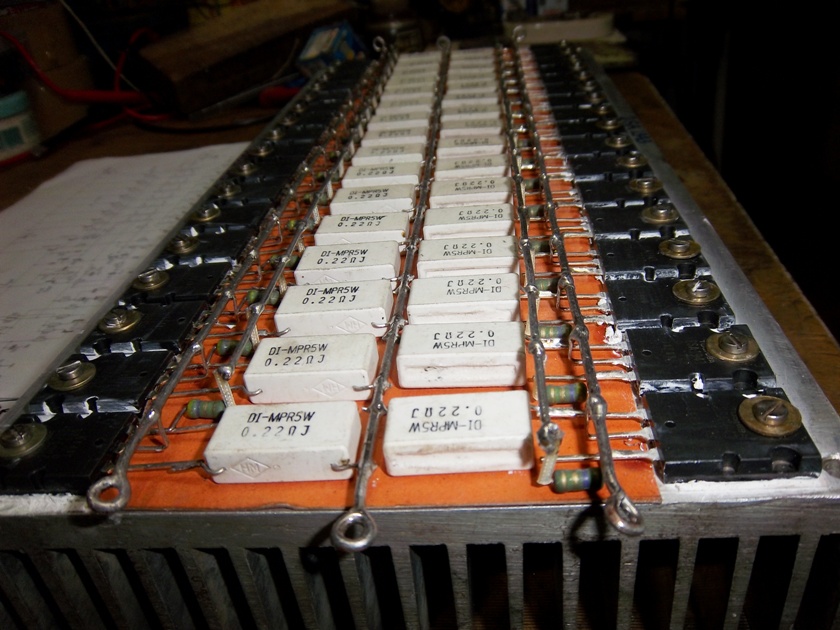
Traffo in picture is already wound with single cotton covered wire and i will use same for secondaries .Yeasterday from 9.00 A.m to 11.30 P.m was busy with my Learned friend Bunty Verma to modify my old winding machine. Now I can wind up to 12 K.v.a E.I. traffo.Next project is to make a Torrid traffo winding zig as local Torrid traffo winding guy can only wind punny torrids as he made for Andrew Lebon. Regardind Rod Elliots 117 project I am working on that too .Here is a photo with some modifications.
Regards
Attachments
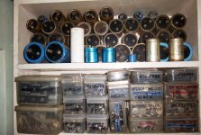
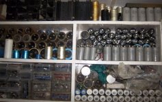
Yeah it is good to learn,but not to become copy cat.One should use his own creativity also.As for me I am always a learner and wish to die as a learner.some more photos
Attachments

http://www.diyaudio.com/forums/atta...4-has-any-one-built-1kw-amp-copy-100_1711.jpg
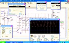
imagine a simple circuit made with one LM317 and a couple of "passive"" PNP transistors which is actually a very common practice when it comes to a DC regulator ...Given enough trafo enough capacitance and proper construction /heatsink and wiring you will be able to drive a resistive load to almost 20A .
Measure carefully and you will notice that even though construction is good and wiring is far thicker than 4mm needed for 20A the psu is not fully regulated even though measures 13.8 in the output with load conditions it goes down for a few mv ..... Just a few but still goes down
This is probably cable wiring connection losses you may increase wiring thickness tighten up all connections but it will still go down for a few mv may be less than before but still go down .
Now remove feedback trace from inside the pcb and sense it directly on the load you will notice that only in this case you have a fully regulated power supply .
My example has no actual use in your case but is a good lesson on power distribution and cable and wiring losses .Notice this example is with very easy conditions ....That is DC and resistive load ...Audio signals and supplying audio amps with power is totally different ballgame .
In your construction if you supply somewhere in the middle even with 6mm of cable which is good enough for 25A at DC conditions and resistive loads expect to loose enough voltage on the sides enough to destroy one of the side transistors and then others will simply follow .
If you supply with 6 or 10 mm on any of the sides at full load conditions you will loose almost 5 volt on the other side ( my estimation ) which means that the amp will simlply blow with in seconds .
Only possible solution is to supply the board 4 times side middle middle side but then again the amp will fail in long run in the area that has the longest cable from the power supply
Only real solution will be a proper pcb designed and properly supplied side to side or with any side middle solution to guaranty even distribution...
2.5 mm just forget about it especially when your target is 35A in the output
regards
sakis
That's True, And This Is Specially Critical With High-Power/Hi-Voltage Designs, This Is Why Some People With Little Or No Experience Fail On Several Attempts Building a Hi-Power Amp Just From Schematic And Give No Attention To The PCB Design, Traces/Wiring Thickness, And Other Sort Of Details Involved, Remember, Great Part Of Successful DIY Is The Attention And Care To Details In The Construction Processes And Obviously Electronic Skill Level To Accomplish The Task, Just My Opinion....
Best Wishes...
Best Wishes...
- Status
- This old topic is closed. If you want to reopen this topic, contact a moderator using the "Report Post" button.
- Home
- Amplifiers
- Solid State
- Has any one built this 1KW amp?