Unique, very very low THD CFA 120/230W amp
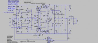
This is going to be my next project of the CFA. Why it is Unique? This is only amp, I know, using OIC(output inclusive compensation, or pure Cherry) and thus lowers crossover output stage distortion. I did simulate similar CFA amp with lateral MOSFET output, but not yet built( I hope Chris will do real world amp of it soon). This one use all BJTs and triple output. This kind of a compensation was discussed a lot(Cherry wrote an article) and D. Self said in his book that is not possible to make practical amp with this as it's to unstable. I think opposite, it is very possible and it should be done. Here I use OIC in combination of the shunt compensation(actually two shunt compensation) and in simulation the triple does not need additional internal compensation, at list in the simulation.
As I think that most people will satisfy with 120 W/8 ohm, 230 W/4 ohm I used only three output pairs. This amp has THD at all frequencies and all powers below 7 ppm, and THD1k below 2 ppm.
I did try different IPS, and going always back to the Baxandall pairs at the input, with diamond input I gain nothing, simple diamond or bootstrapped, and here I use CCM in combination with the Hawksford cascade for the VAS. It is possible to simplify the VAS and not loose in distortion level, and I could show the simplified version too.
Distortion harmonic distribution is quite benign and this is a way to excellent sound. It is DC from the input to the output using DC servo to kip output DC offset below 1 mV. I was trying different ways to connect DC servo with as less as possible influence on the signal path, and thanks to OS I choose this way I used here.
This is just a study as I intend to add all needed protection. First idea is to use capacitance multipliers for the output stage with a protections incorporated on the same PCB and this I've use in my TT amp and it works flawlessly. Other idea is to use output transistors as protection units(not standard current limitation, sound influence is to bad) and not yet sure how to do that.
BR Damir.
Attachments
Last edited:
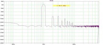
Here are 1 kHz FFTs at different output power, and excellent clipping behavior.
THD at 10 Hz is on the same level, it should produce excellent low distortion bass.
BR Damir
THD at 10 Hz is on the same level, it should produce excellent low distortion bass.
BR Damir
Attachments
Hi Guys
Can you provide a larger schematic, or make the above one expandable? Some of the values are hard to read.
It seems like there are two forms or two definitions for OIC. The Cherry cap is one form. The other is as used on Self's Compact Blameless amp (not that he invented, OIC has been around since the 1970s with other names), where the standard miller cap is split in two with both new caps at twice the value, then a 1k tied from their junction to the output node. There is a transition from OIC to straight miller, so maybe this form needs a name other than OIC (which Doug called it) - transitional OIC...?
I've used the above compensation on both VFA and CFA designs and it seems to work well. I can't read the THD on my Radford analyser.
Great design as usual. What needs to be determined are the real-world impediments or considerations for attaining the simulated performance. Do0 either of you have an APsys2?
Have fun
Kevin O'Connor
We will keep it going , despite the CFA thread off-topic stuff
OS

Hi Guys
Can you provide a larger schematic, or make the above one expandable? Some of the values are hard to read.
Great design as usual. What needs to be determined are the real-world impediments or considerations for attaining the simulated performance. Do0 either of you have an APsys2?
Have fun
Kevin O'Connor
Some Monte-Carlo runs need to be run to determine spreads of parameters and their affect which could impact actual build performance.
I will test any CFA amps (only) with AP2722 and ShibaSoku 725D and others..... BUT, they cant be just pcb for me to load. Stuffed, working boards only.
Personally, still looking for the higher output CFA (approx 250W/8).
THx-RNMarsh
Last edited:
Very nice .... I see some very familiar techniques here.
I guess I might "borrow" some of yours .. too.
We will keep it going , despite the CFA thread off-topic stuff
OS
Thanks OS, I hope you can find something interesting to use in your designs.
Hi Guys
Can you provide a larger schematic, or make the above one expandable? Some of the values are hard to read.
It seems like there are two forms or two definitions for OIC. The Cherry cap is one form. The other is as used on Self's Compact Blameless amp (not that he invented, OIC has been around since the 1970s with other names), where the standard miller cap is split in two with both new caps at twice the value, then a 1k tied from their junction to the output node. There is a transition from OIC to straight miller, so maybe this form needs a name other than OIC (which Doug called it) - transitional OIC...?
I've used the above compensation on both VFA and CFA designs and it seems to work well. I can't read the THD on my Radford analyser.
Great design as usual. What needs to be determined are the real-world impediments or considerations for attaining the simulated performance. Do0 either of you have an APsys2?
Have fun
Kevin O'Connor
Above schematic is expandable, look left lower corner.
Damir
Some Monte-Carlo runs need to be run to determine spreads of parameters and their affect which could impact actual build performance.
I will test any CFA amps (only) with AP2722 and ShibaSoku 725D and others..... BUT, they cant be just pcb for me to load. Stuffed, working boards only.
Personally, still looking for the higher output CFA (approx 250W/8).
THx-RNMarsh
I can't get an answer from you, what did you do with the GainWire PCB I've sent to you??
Way you did not say that you want assembled board only?
BR Damir
I can't get an answer from you, what did you do with the GainWire PCB I've sent to you??
Way you did not say that you want assembled board only?
BR Damir
Hi D -
It is still sitting on my desk. I thought I would have time to assemble, but I dont have the time any more.
But I do have time to do measurements if assembled. PM me if need to.
THx-RNMarsh
Hi Guys
It does not expand and the usual little expander icon is not there. Could you reload it?
Have fun
Kevin O'Connor
Is this good enough?
Damir
Attachments
Explain Q25/Q26 ??
Oh , you just have it drawn strange ? CM ?
OS
It is just strange drawing, as I added those transistor later to make CMs(Q25, Q6 and Q26, Q8).
Dado
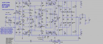
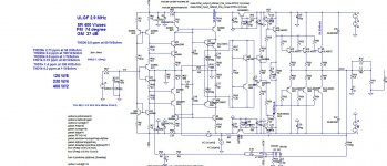
This one is with a current conveyor VAS, low voltage input V to C convertor and differently connected DC servo.
This one I like better, for some people to complex I presume.
BR Damir
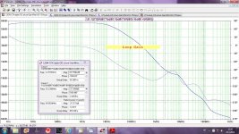
Here are the Loop Gain(LG) and 1 kHz FFT at 1 W/8 ohm.
BR Damir
Attachments
This one is with differently connected non inverting DC servo, very good clipping behavior, very low distortion and very high SR, perfect amp!!
Attachments
-
 120W-CFA-triple-OIC-shunt-GainWireVAS2-15V-DCservo-CCS1-sch.gif183.8 KB · Views: 1,198
 -
 120W-CFA-triple-OIC-shunt-GainWireVAS2-15V-DCservo-CCS1-FFT1k50W.gif26.8 KB · Views: 601
 -
 120W-CFA-triple-OIC-shunt-GainWireVAS2-15V-DCservo-CCS1-FFT1k1W.gif22.2 KB · Views: 265
 -
 120W-CFA-triple-OIC-shunt-GainWireVAS2-15V-DCservo-CCS1-clipping.gif14.2 KB · Views: 272
This one is with differently connected non inverting DC servo, very good clipping behavior, very low distortion and very high SR, perfect amp!!
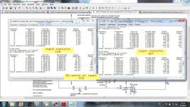
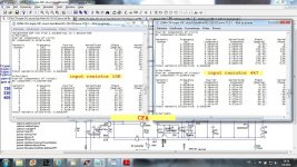
After reading the chapter about input current distortion in D. Self book I simulated that and came to surprising result, with DC servo connected on this way that distortion was unacceptable high with input resistor of 4k7(R61 resistor part as input LF filter). With as usually used 1k, it was not so high nut still the source output impedance could worsened that.
After that I simulated with DC servo connected in convectional why, at the feedback input and distortion was much lower. I am not sure way is that for the moment, but I suggest not to use that so "elegant solution" to connect DC servo outside the signal amplification.
BR Damir
ps. First table shows high distortion of unconventionally connected DC servo, and second table shows quite low distortion increase when DC servo connected as in attached schematic.
Attachments
This one is with differently connected non inverting DC servo, very good clipping behavior, very low distortion and very high SR, perfect amp!!
Are pre-driver, driver, and final transistors must be on same heat sink?
Are pre-driver, driver, and final transistors must be on same heat sink?
Idea with double symmetric BJT bias spreader was to have small separate heat sink for the drivers with one BJT of the bias spreader mounted together, and other one mounted on the main heat sink with the output transistors.
It could be possible to mount all on the same main heat sink and then you can use simple one transistor bias spreader, but in my opinion thermal tracking is superior with separate heat sinks, as the drivers are not additionally heated by the output transistors.
- Home
- Amplifiers
- Solid State
- Unique CFA 120/230W amp