Idea with double symmetric BJT bias spreader was to have small separate heat sink for the drivers with one BJT of the bias spreader mounted together, and other one mounted on the main heat sink with the output transistors.
It could be possible to mount all on the same main heat sink and then you can use simple one transistor bias spreader, but in my opinion thermal tracking is superior with separate heat sinks, as the drivers are not additionally heated by the output transistors.
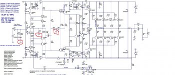
Q23 on driver's heat sink and Q24 on main heat sink?
I will sim your bias servo.
What do you think about bias servo that use at Ostripper's EF3 Slewmonster?
Q23 on driver's heat sink and Q24 on main heat sink?
I will sim your bias servo.
What do you think about bias servo that use at Ostripper's EF3 Slewmonster?
It is excellent one, but a simple one serves the purpose good enough.
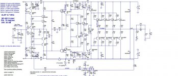
200W/8 and 400/4
This is 200W/8ohm CFA, SR 450V/us, THD1k full power on 8 ohm 0.0002%, THD20k full power on 8 ohm 0.0016%.
This amp is quite simple, with very low distortion, high slew rate, good phase margin and gain margin, excellent clipping behavior thanks to the supper pair VAS.
I simulated supper pair cascaded VAS, but distortion did not go lower and it looses some headroom because of cascade and it needs separate higher voltage power supply for the IPS to counteract that.
Damir
Attachments
Hi Damir,
Interesting variant. Like the use of the super pair VAS. Do you envisage any stability problems with this? Also, what precautions can be taken in case of instability?
Paul
Hi Paul,
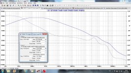
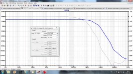
thanks for your liking. From the Loop Gain I don't see any stability problem, I simulated it with output capacitor up to 2 uF with no hint of any instability, interesting thing is that most critical capacitive load is around 10 nF and this is where some exotic cables are.
Damir
Hi Paul,
thanks for your liking. From the Loop Gain I don't see any stability problem, I simulated it with output capacitor up to 2 uF with no hint of any instability, interesting thing is that most critical capacitive load is around 10 nF and this is where some exotic cables are.
Damir
Hi Damir,
Global stability looks good. Was thinking more about local instabilities due to the super pair. But you do have reasonable shunt loading on the VAS output and that may help with this?
Paul
Now add HEC into the mixGive it a try?
Look here, it is not global NFB, but it uses a new kind of EC thanks to Sergio.
http://www.diyaudio.com/forums/solid-state/260308-gainwire-ngnfb-classb-poweramp-11.html#post4045598
Hi Damir,
Global stability looks good. Was thinking more about local instabilities due to the super pair. But you do have reasonable shunt loading on the VAS output and that may help with this?
Paul
This is from "LOOP GAIN CALCULATION WITH SPICE by Alberto Petrini"
"This circuit can be inserted anywhere in the loop, but if you have many feedback paths,
the circuit must be added where the different paths join together (otherwise the results
will obviously be incorrect). The best you can do is to add this circuit after the summing
point of the feedback, on the error signal path. If you do this, the transfer functions that
will be calculated will have a physical significance.
"
Damir
Good amplifier, dadod.
Hope many will build, when you get all things ready ....
Isnt there a PCB misssing?
Thanks lineup. Maybe someone will offer some help with the layout?
...Who knows ,maybe I will give a try to layout this beautiful schematic .....
That will be great, thanks Alex.
The power ground and the signal ground should be separated and connected via 10R resistor.
This is not showed on the schematic as this is LTspice schematic for simulation. The signal grounds are circled in red on the attached schematic.
This is not showed on the schematic as this is LTspice schematic for simulation. The signal grounds are circled in red on the attached schematic.
Attachments
This is from "LOOP GAIN CALCULATION WITH SPICE by Alberto Petrini"
"This circuit can be inserted anywhere in the loop, but if you have many feedback paths,
the circuit must be added where the different paths join together (otherwise the results
will obviously be incorrect)
Hi Damir
Firstly, thanks for the copy of Petrini that you sent me, it's better formatted than my previous copy.
His advice is sensible but very broad, he doesn't discuss push/pull situations where a test balun is needed.
Probably no problem, you seem to have tested carefully, but Paul's question interests me too.
I would like to study this and learn more about CFAs, could you post the ASC?
Best wishes
David
Thanks Damir.
The ASC you posted is presumably a test version because the input capacitor is disconnected and stability is barely adequate - Global loop is the problem and the closed loop response reflects this.
With the input capacitor reconnected the Global loop is still the less stable of the loops but is OK and so, naturally, is the closed loop response.
I was surprised when I first noticed how much effect the input capacitor can make in a VFA, seems to be the same for CFAs too.
I will experiment with the test Balun tomorrow.
Have you experimented to look for indeterminate VAS current problems?
Seems if the loop gain is increased then a CFA may be vulnerable to the same excessive sensitivity to component variation as a complementary VFA.
Best wishes
David
- Home
- Amplifiers
- Solid State
- Unique CFA 120/230W amp