Hi,
Not sure what sort of thing you are looking for. Here's a bullet-proof circuit that will protect your speakers against dc offsets of 0.6V or more. It has a detection circuit that triggers an opto- thyristor and then disconnects the speaker via a relay. It keeps the speaker disconnected until the dc offset is gone AND you have reset the circuit via a push switch. You need to access the speaker outputs and the + and - supply rails and ground.
If this is the sort of thing you want let me know and I'll explain it in detail.
Attachments
No passive device is going to be able to detect DC and disconnect the speakers...at least that I know of.
Elliot Sound has a PC board (it's very small) that simply needs population and a relay (and the wiring to the board) that does the job in about as small a space as possible.
http://sound.westhost.com/project33.htm
Also..here is a design that I've used a few times...but if space is a concern I'd consider the ESP board.
Attachments
It won't protect against DC but......
Hi,
you may want to consider some polyswitches in addition to the dc protection circuit. They are current tripping devices so protect against over power situations, which a DC protection circuit won't....
Link here: http://www1.jaycar.com.au/productVi...xxx&pageNumber=&priceMin=&priceMax=&SUBCATID=
Note Jaycar have a much better explanation about choosing them in their paper catalog.... I prefer to put one on each driver rather than just on the speaker input.
Tony.
Daniel,
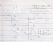
Here's the circuit explanation. The circuit is designed for an amp with split rail supplies of about +/-36V. Component values can be adjusted for other rail voltages.
The left half of the diagram is the dc detector. The speaker signal is fed through a 10k resistor into a 50uF non-polarised cap. These set the time constant for the trigger. The transistors should have betas >100 and Vce >rail voltage. The two 2.7k resistors set the "on" current through the LED of an opto-SCR.
The right hand portion controls the speaker relay. When the amp is powered-up, the relay is initially open-circuit (speaker disconnected). The 2200uF cap charges up throught the 2.7k resistor and then the relay is activated, driven by the transistor. This provides a few seconds of turn-on delay thus mitigating any turn-on thump from the amp. The cap stops charging when the 24V zener holds the voltage at the transistor's base. This circuit uses a 24V relay.
When dc is detected the opto-SCR is triggered and the SCR, aka thyristor, switches on. It remains on until no current flows through it. It pulls the transistor base to ground and turns off the relay. The circuit will remain in this state even if the dc condition goes away. The only way to "reset" the thyristor is to short-circuit it using the push-switch, or by powering down the amp for a few seconds. If the dc condition still exists, pushing the switch will have no effect and the speaker will remain disconnected. (The cap also slugs the rate of voltage rise across the thyristor to prevent it from self-triggering due to junction capacitance).
The 10k resistor is a bleed for the cap. The 1N4001 diode shorts reverse currents from the relay coil. The 0.01uF cap prevents arcing at the relay contacts when the speaker is disconnected. That's about it - the 2.7k resistors should have about 1W power rating. For transistors I used ZTX653/753 but any similar transistors will do. Use a good quality relay to preserve sound quality - mercury contacts or whatever - and ensure it can handle the speaker currents, a 10A relay normally suffices.
I can assist with adjusting component values to suit your amps power supply rails, just ask. And if the diagram isn't clear enough I'll send you a new one.
passive possibility
The trouble with a passive system is that relay power is needed. A really simple circuit could be made with a "normally closed" relay. Just put the relay coil in series with a resistor and connect across the speaker outputs. A cap across the coil to slug the response a little. The line to the speaker goes through the n.c. relay contacts. If a dc level appears that is high enough to drive the relay it will disconnect the speaker. This is belt and braces and may save your cones from the most common failure which is the output going short to one of the rails.
The trouble with a passive system is that relay power is needed. A really simple circuit could be made with a "normally closed" relay. Just put the relay coil in series with a resistor and connect across the speaker outputs. A cap across the coil to slug the response a little. The line to the speaker goes through the n.c. relay contacts. If a dc level appears that is high enough to drive the relay it will disconnect the speaker. This is belt and braces and may save your cones from the most common failure which is the output going short to one of the rails.
Which is exactly what the Velleman kit does.If a dc level appears that is high enough to drive the relay it will disconnect the speaker.
An externally hosted image should be here but it was not working when we last tested it.
you can try something more greek
")
http://users.otenet.gr/~athsam/protection_1.htm
amp for sale Yamaha p2200
Ok, my amp is for sale.
230w 8ohm rms continuois sine wave input. One channel is broken. One supply cap will need replacing.
Yamaha guy in bendigo said on average the broken channel in this amp cost $150 to repair. JKL capacitors quoted me around $150 for 2 new supply caps including postage (depends on aussie dollar of course) I no longer need this as i got myself a soundking amp and i am now working almost 50 hours a week so yeah... There is NO glue on the caps!! It is all there, the case looks like it woulda new. I am after $200 ONO. DOnt hesitate to ask questions.
www.geocities.com/elphocfa/yamaha
Daniel
Last edited by a moderator:
DC detector / Speaker Protection Circuit
Hi EchoWars,
I am very interested in your DC detector / speaker protection circuit.
Is it working well for speaker protection?
Is the muting function OK?
I want to have your comment about the circuit.
Thank you for your assistance.
Dominic Ko
Hi EchoWars,
I am very interested in your DC detector / speaker protection circuit.
Is it working well for speaker protection?
Is the muting function OK?
I want to have your comment about the circuit.
Thank you for your assistance.
Dominic Ko
Attachments

polyswitches? better check the characteristics of them before deciding to use them. they are basically current dependent resistors, and do not present an open circuit when tripped, they only double in resistance. they are intended as overcurrent "foldback" devices only. they are also prone to literally catching fire if you exceed their voltage and current ratings. Peavey uses them in their pro-audio speaker crossovers to protect tweeters, which the polyswitches really don't do well. they certainly can't operate as dc protection devices on a speaker line.
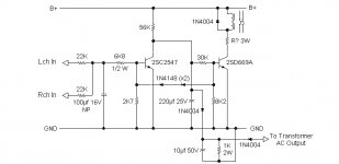
dc protection circuits should be kept as simple as possible. a simple 2 pole low pass filter with gain and full wave rectification should suffice. the filter should have a rollover of about 5hz. the rectifier output can simply turn on a transistor placed across the base circuit of a relay driver, cutting off base drive to the relay driver if dc or up to 5hz is detected at the amp output. gain should be about 6 or 7, so that a 100mv offset shuts off the relay.
even simpler is the one shown below, it includes a turn-on delay, dc protection, and inputs from a safe area detector circuit. you can ignore the safe area components and concentrate on the dc protect circuit. it's simple, uses 3 transistors in addition to the relay driver. the turn-on delay circuit is fed by the +12v rail BTW. it's simple and very effective, and takes up all of 2 sq-in of board space. use a good high current 4PDT relay for the speaker relay. you can also add a mute button using a resistor and a switch to turn on Q206.
- Status
- This old topic is closed. If you want to reopen this topic, contact a moderator using the "Report Post" button.
- Home
- Amplifiers
- Solid State
- DC output protection circuitry