As D103 is reverse biased, the 1.07v seems to be coming in from the circuitry above your schematic section. It's probably coming in from that MU (mute) pin on CB102 which then points you back to the System Control IC301. You could try lifting R329 in the Mute line to see what happens.
Hey Guys,
Right, turns out that all the PCB's connectors grounds are in series and isolated with small caps (C715, C127 for example - Is this common?), meaning because I didn't have all the boards connected (I thought isolating them would make it easier to diagnose, not worse!) that I had all those high voltages as half of the PCB wasn't grounded.
Now, I have the rear power amp connected fully as well as earthing out the two E pins on CB701. I didn't have a heap of time tonight to do too many measurements however I found that when the amp first powers up I have around 22v on the LHS of R808 and 0.7V on the RHS (which is leading from the rear power amp to PROTEC and hence turning it off).
THEN, with the mains relay shorted open after about 7 more seconds the output relays (RY101 and RY701) turn on and the voltage on both sides of R808 drops to about 100mv. Then, if I press the power button again on the amp it turns on and stays on.
So, this is what I'm thinking: RY101 and RY701 should be turning on earlier (rather than about 10 seconds after the button is pressed/the mains relay turns on) before the IC checks the PROTEC pin (which is around 3 seconds). Perhaps one of the caps has lost its charging capabilites and is causing this? What do you guys think? How do I even easily test for this besides pulling them all out?
I also tested Q717A/C and they have the correct voltages on them (when the amp stays on after the relays click in), so I don't think it's them.
Anyway, let us know your thoughts!
Cheers,
Felix
EDIT: Or, shouldn't this initial 22V on the left of R808 (before the relays turn on) be there anyway, regardless of what the output relays are doing?
Last edited:
Measured time vs. theoretical time would be a pretty good indication of a timing capacitor's worthiness. A rough check of the RY101 time constant circuit does show a turn on time of around 10 seconds unfortunately.
22v at the o/p of the rear amp before the relays turn on sounds a bit fishy. Funny how it's about half of the +47v supply, I wonder if the -47v is slow to come up for some reason at the rear amp?
You could always try lifting R808 if you still have the safety resistors fitted in the +-47v supplies.
22v at the o/p of the rear amp before the relays turn on sounds a bit fishy. Funny how it's about half of the +47v supply, I wonder if the -47v is slow to come up for some reason at the rear amp?
You could always try lifting R808 if you still have the safety resistors fitted in the +-47v supplies.
Hey Guys,
Finally have gotten enough time again to dust off this amp and have another play, after a bit of measuring with this rear power amp I am now fairly certain it's something to do with some of the transistor/cap timing!
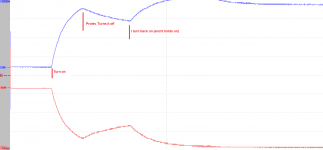
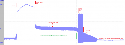
I've noticed that measuring at R763/R744/R808 when you first power on the voltage rises quickly to 22V, then up to around 33V before powering it's self off (with the 0.7V on the RHS of R808, leading to PROTEC).
This then drops the voltage down to around a -400mV DC, (however looking at my DSO trace there is a reasonable AC fluctuation), which if turned back on again here it will stay on forever at this same voltage.
It then does a strange thing if left here for about 6 seconds (without turning back on) as it will increase this AC amplitude, then back off all the way to -15V where it will then discharge slowly (over a few minutes) back to 0V.
I've included a trace of these measurements, plus one of the two supplies from the bridge which shows that they are quite symmetrical in their behavior.
Any thoughts on this? I'm thinking it's a dodgy cap on the negative supply somewhere (C737, C735, C738), however that's pretty much a guess...
Sorry this thread has died a bit, I've really appreciated the help so far!
Regards,
Felix
Finally have gotten enough time again to dust off this amp and have another play, after a bit of measuring with this rear power amp I am now fairly certain it's something to do with some of the transistor/cap timing!
I've noticed that measuring at R763/R744/R808 when you first power on the voltage rises quickly to 22V, then up to around 33V before powering it's self off (with the 0.7V on the RHS of R808, leading to PROTEC).
This then drops the voltage down to around a -400mV DC, (however looking at my DSO trace there is a reasonable AC fluctuation), which if turned back on again here it will stay on forever at this same voltage.
It then does a strange thing if left here for about 6 seconds (without turning back on) as it will increase this AC amplitude, then back off all the way to -15V where it will then discharge slowly (over a few minutes) back to 0V.
I've included a trace of these measurements, plus one of the two supplies from the bridge which shows that they are quite symmetrical in their behavior.
Any thoughts on this? I'm thinking it's a dodgy cap on the negative supply somewhere (C737, C735, C738), however that's pretty much a guess...
Sorry this thread has died a bit, I've really appreciated the help so far!
Regards,
Felix
Attachments
Hi again. I never thought before, I've got a Yamaha RVX-667 7.2 amp and that has speaker relays clicking about 6 seconds after power-up if that helps, you never know it might be the timing Yamaha always uses. Alternatively, perhaps your Protec circuit is checking too early but it seems to be set by crystal controlled IC301 so seems unlikely. The general idea would be for it to check DC conditions are good enough before operating the speaker relay(s).
Some designs can be a bit marginal on protection, fine when they're new but throw in a little cap drift/leakage and then they're not fine, I've experienced it myself on a Harman Kardon 5.1 sub not coming out of standby and the relevant cap had only dropped in value 10% and wasn't leaky.
Another thing I think I've noticed is that you're looking at R808 in the centre amp circuit, the rear amp is IC702 and has no protection according to the block diagram in the full schematic.
Sorry I can't be more help ATM.
Hi sbrads,
Thanks for your response, that's interesting to know about the RVX-667. I think you're right, that is the correct timing for the output relays, it was just coincidental that it occurred at similar timing to whatever is my problem.
My mistake on which amp I have been looking at as well, it is the centre one (I had forgotten after all this time)
I spent quite some time today thoroughly measuring what is happening, and this is what I propose:
On initial power-up either Q713 (and hence) Q717A isn't turning on quick enough (well before PROTEC is checked), as one of the capacitors in the timing circuit is taking too long to charge (however will be enough if the amp is quickly turned back on). This is why it initially goes high, because the negative rail isn't activated.
Is this plausible? If so, which capacitors? I couldn't figure out exactly how the circuit worked so I'm thinking I might just replace C734, C736, C738, C735, C737 and see how it goes...
Thoughts on doing this?
Also, this holding on (if I quickly turn it back on) has only been happening ever since I have put in these sacrificial resistors (100R), which drops the rail voltages from +- 47v to around +- 37v.
Thanks again!
Felix
yamaha
Sorry i didn't read all the posts about the problem, but you should enter the service mode of your receiver first(i think it should have this feature). So you will find out what kind of protection is working. Then keep in mind that the protection itself is more reliable then the circuit it protects.So look problem in circuit first. Yamaha receivers from my experience are not very reliable. In example DC protection can be triggered because dc offset voltage which can be caused by the amps input differential pair transistors aging. Which changes transistor hfe current gain. And so on ... Do the repair step by step
Sorry i didn't read all the posts about the problem, but you should enter the service mode of your receiver first(i think it should have this feature). So you will find out what kind of protection is working. Then keep in mind that the protection itself is more reliable then the circuit it protects.So look problem in circuit first. Yamaha receivers from my experience are not very reliable. In example DC protection can be triggered because dc offset voltage which can be caused by the amps input differential pair transistors aging. Which changes transistor hfe current gain. And so on ... Do the repair step by step
Also, this holding on (if I quickly turn it back on) has only been happening ever since I have put in these sacrificial resistors (100R), which drops the rail voltages from +- 47v to around +- 37v.
Felix
That seems to indicate something doesn't like high voltages, like caps, but transistors can go a bit leaky at high volts also which doesn't help to reduce the possibilities.
For caps, I would first change the feedback electrolytic C702, the reason being that the amp AC gain is controlled by feedback R745/R709 ratio and is high (x160-ish) but the DC gain is unity because of the infinity resistance at DC of C702 being in series with R709. Therefore if it's leaky, the DC gain shoots up and input errors get amplified up at the output.
For transistors, the input pair would be favourites as a bit of leakage on one half of the output stage trying to cause voltage offset would get tuned out by the feedback if the rest of the amp was OK. An output transistor would have to be very leaky to do anything bad and as you don't have a high current consumption it would likely rule out the output stage.
Hi guys, thanks for your replies.
sraudio - for this receiver there is no service mode, only a protection pin (labeled PROTEC) that senses (and checks on startup) DC offsets from various parts of the circuits, and shuts the unit off.
sbrads, that makes sense, so I went with your advice and have changed C702, along with C701, C713, C714, C736 and C737 for luck, however same thing is happening...
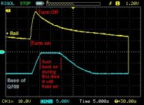
It's quite tedious measuring as once the receiver stays on all the DC voltages seem fine, it's just this startup that is the problem. Measuring the emitters of Q706 and Q709 they are fine throughout (as expected really), however the base on Q709 always seems to drop back to -10v on standby, and then takes a little longer (~4 seconds) to reach -0.1V). As can be seen from the attached scope graph, this value is reached after the PROTEC timeout, which shuts the unit off as Q709 is yet to switch (but this -0.1v holds for nearly 10s, which if I switch the unit on it will stay on).
So, I'm thinking I might replace Q706 and Q709 next, however finding the exact transistor is hard. Would these suit? http://www.jaycar.com.au/products_uploaded/ZT2283%20-%20PN100.pdf (Shop is down the road...)
Then again, why are the majority of voltages dropping back to this negative voltage when it shuts down? Both rails from the supply come up just as quick I'm pretty sure, maybe not fast enough?
Finally, I brushed my hand over IC702 while testing and noted that if the unit is powered on (following the above procedure) that this IC gets quite hot... not sure if this is normal for these sorts of IC, but given I have no outputs (and hence no current draw?) I am concerned by this. I still have the limiting resistors from the bridge, however this IC is also powered from the +26.3 and -26.9 taps from the transformer.
Sorry for the long read!
Regards,
Felix
sraudio - for this receiver there is no service mode, only a protection pin (labeled PROTEC) that senses (and checks on startup) DC offsets from various parts of the circuits, and shuts the unit off.
sbrads, that makes sense, so I went with your advice and have changed C702, along with C701, C713, C714, C736 and C737 for luck, however same thing is happening...
It's quite tedious measuring as once the receiver stays on all the DC voltages seem fine, it's just this startup that is the problem. Measuring the emitters of Q706 and Q709 they are fine throughout (as expected really), however the base on Q709 always seems to drop back to -10v on standby, and then takes a little longer (~4 seconds) to reach -0.1V). As can be seen from the attached scope graph, this value is reached after the PROTEC timeout, which shuts the unit off as Q709 is yet to switch (but this -0.1v holds for nearly 10s, which if I switch the unit on it will stay on).
So, I'm thinking I might replace Q706 and Q709 next, however finding the exact transistor is hard. Would these suit? http://www.jaycar.com.au/products_uploaded/ZT2283%20-%20PN100.pdf (Shop is down the road...)
Then again, why are the majority of voltages dropping back to this negative voltage when it shuts down? Both rails from the supply come up just as quick I'm pretty sure, maybe not fast enough?
Finally, I brushed my hand over IC702 while testing and noted that if the unit is powered on (following the above procedure) that this IC gets quite hot... not sure if this is normal for these sorts of IC, but given I have no outputs (and hence no current draw?) I am concerned by this. I still have the limiting resistors from the bridge, however this IC is also powered from the +26.3 and -26.9 taps from the transformer.
Sorry for the long read!
Regards,
Felix
Attachments
Hi,
Can you do some IC301 pins voltage reading. Read the pins voltage when the power amplifier it is turn on and fail. Do the same test by trying to make the amplifier stay on and read the pins. It will tell you what it is causing the problem. A +5 volt at the Protect pin means that you have a problem with one of your speaker outputs. Please post the reading .
Failed condition
PDET - pin 24 - read = ?
ProtecT - pin 23 - read = ?
pwrly - pin 7 - read = ?
running condition
PDET - pin 24 - read = ?
ProtecT - pin 23 - read = ?
pwrly - pin 7 - read = ?
Right, time to try something new. Get a permanent connection to Q709 base so you don't have to probe all the time, measure the voltage with a DVM and get used to how long it takes to charge up from -10v to 0.1v with a few turn-ons. Now heat up areas of the board with a hot air gun (hair-drier will do) and repeat. You could also try freezer spray as well if you have any. Look for variations in the charge time, with a bit of luck you'll get a large change in a small area of the board which should help to narrow the range of possible faulty components somewhat.
A quick look at IC702 datasheet shows a quiescent current of typically 60mA, max 120mA. At 52v total supply that's 3-6w dissipation which could be very hot depending on heatsinking.
A quick look at IC702 datasheet shows a quiescent current of typically 60mA, max 120mA. At 52v total supply that's 3-6w dissipation which could be very hot depending on heatsinking.
Last edited:
sbrads,
After convincing my girlfriend that it's perfectly acceptable to be taking her hairdryer out into the shed, I have tried your suggestion and have found that when I heat up the effect power supply (namely C747 and C746), Q709 base voltage on power off drops to ~-4v instead of -9v as would happen at normal temperatures.
So, my thought is that one of them (C746? I'll replace both anyway) is leaky, resulting in the whole protect circuit being pulled low through D712.
The only other cap in this area (where I am directly heating) is C745, so I might as well replace that as well.
What are your thoughts on this?
Felix
- Status
- This old topic is closed. If you want to reopen this topic, contact a moderator using the "Report Post" button.
- Home
- Amplifiers
- Solid State
- Yamaha RX-V390 - Circuit Protection