Hey Everyone,
I have a RX-V390 which will turn on for about 3 seconds and then turn off due to the short circuit protection (apparently). I have read a heap of other threads of similar receivers doing the same thing which have made me narrow down what I am looking at however I just can't seem to make my mind up on what's wrong. I have pulled out and disconnected the Tuner, Input and Rear Power Amp PCB which has narrowed it down to the front control board and the main power amp. I have measured the speaker outputs and there is no voltages on any of the channels and all the fuses are intact.
Can anyone explain these attached circuits to me about how the detection circuit works?
From my understanding, pin 'PROTEC' should be high (5v) however mine is low, hence why it shuts down. Tracing back from the pin however gets me to the main power board with transistors Q118 and Q119 (see attached). How does this work? The collectors of the transistors are connected to the PROTEC pin, however being an input I don't see how this helps.
Anyway, testing the rest of the voltages in the 'PROTECTION' area has lead me to the readings marked in red on the diagrams.
Looking at Q127 has me to believe that a fault is here as I have 46v on the collector which isn't tied to anything (I have disconnected the rear power amp connector).
Any ideas? Does this protection circuit look for leakages into the ground rail or something? It's hard to get proper measurements with the largish caps (C132/C133) as they are still charging up until the 3 seconds where the main power relay clicks off from the IC. This does mean that transistors Q117 and 116 don't turn on which could potentially be why I don't have any voltage drops over R171 D106 and Q127 perhaps?
This is probably really vague however ANY help would be appreciated, if you require anything else (the entire service manual?) let me know! =)
Thanks,
Felix
Attachments
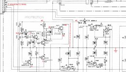
My guess is you have 0.7v on the base of Q119, this would make PROTEC low, the 5v pullup voltage coming from IC301 I guess but being pulled down in your case by Q119 being turned on. If so, you're then looking for a DC offset at the output of the power amplifier being fed into the base of Q119 via one of the various resistors and diodes at the amplifier output, eg R165 (overcurrent of left OR right amp output stages) R157 (front left amp DC offset), R158 (front right amp DC offset).
Q127 gets its 46v via a relay coil, something to do with turning the centre speaker on. If Q117 collector goes low after a few seconds I don't think you have a problem in the C132 mains input detection time delay circuit.
My guess is a blown output stage.
Q127 gets its 46v via a relay coil, something to do with turning the centre speaker on. If Q117 collector goes low after a few seconds I don't think you have a problem in the C132 mains input detection time delay circuit.
My guess is a blown output stage.
Hey sbrads,
Thanks for your reply, that makes a lot of sense now, I have no idea why it didn't occur to me about a 5v internal pullup...
I have started measuring the front power amp circuits and you are right, there is a 0.65v DC offset at the R165/R157/R158 junction. I tried tracing back further than this and comparing to the schematic however it's hard when the amp will only stay on for about 3 seconds and a lot of the circuits are yet to reach a steady state.
To determine which channel was blown I de-soldered R158 and the same problem occurred (still had a 0.7 offset), so I also de-soldered R157 and it stayed on! This made me think it was a problem with the left channel so I re-soldered in R158 (right channel) and the problem came back!
This meant that I had to have both left and right channels disconnected for it to stay on. I then removed R165 (the overcurrent protection) and it made no change, it would still turn off unless both R157 and R158 were disconnected.
So, what does this mean? It's not a problem with the specific channel and it's something common between them both?
Let me know what you think!
Regards,
Felix
I suppose the -46v supply might be missing. Not likely though.
I think at this stage it might be best to leave the power off and go looking for shorted transistors around the output stages as they usually go short when they fail. I would be a bit careful about removing protection for test purposes unless you can put 10R - 100R 1/2W - 1W (depending on quiescent current) resistors in series with each supply as sacrificial lambs. Meanwhile I'll give it some more thought.
I think at this stage it might be best to leave the power off and go looking for shorted transistors around the output stages as they usually go short when they fail. I would be a bit careful about removing protection for test purposes unless you can put 10R - 100R 1/2W - 1W (depending on quiescent current) resistors in series with each supply as sacrificial lambs. Meanwhile I'll give it some more thought.
Common to both amps where it would cause +ve offset at both L/R outputs:-
1. Open circuit track on the -ve rail. Ohms test from the bridge to the output trannys.
2. Low capacitance on -ve reservoir cap C141, lots of ripple. Parallel it with another cap.
3. Both amps blown. Could a speaker have been wired between L & R?
1. Open circuit track on the -ve rail. Ohms test from the bridge to the output trannys.
2. Low capacitance on -ve reservoir cap C141, lots of ripple. Parallel it with another cap.
3. Both amps blown. Could a speaker have been wired between L & R?
Just went and measured, I have both +-46v supply so that's fine.
I checked for continuity on all of the transistors in the front power amp and none were shorted.
Resistance testing from the negative side of bridge to the collectors of Q129A and Q130A gave me 0.2 ohms (the same as measuring from the positive side to Q129C and Q130C) so it's not an open track.
I'll try and test C141 if I can find a large enough cap (I would assume I would want something of similar size… I have a heap of old computer PSU’s kicking around and one has a 470uf 200v one, would that suit?)
Is the best option just to solder this onto the bottom of the board? I think my multimeter only measures capacitance up to 100uf, so wouldn't be worth unsoldering it?
Both amps could be blown, that is entirely possible. I found this receiver on the side of the road (hard rubbish haha) so I have no idea the history of it. I had been wanting to get a 5 channel to run some speakers out into our kitchen and couldn't believe my luck when I found it in such good condition (besides it not working...)
So yes, anything could have happened.
I have checked for open circuits on the 4 fuse resistors and they all seem fine...
Is there any way for checking capacitors easily in circuit (just to get an indication of dead/not)?
Thanks a HEAP for your help so far!
Cheers,
Felix
Hi,
If you check the collector of Q129 and Q130 it will tell you which of the channel make the amplifier goes into protected mode. A high voltage in the collector means that you have a bad output transistor. It should read almost zero. I do not know if the 3 seconds allow you to read the voltage but you do not lose anything by trying it.
If you check the collector of Q129 and Q130 it will tell you which of the channel make the amplifier goes into protected mode. A high voltage in the collector means that you have a bad output transistor. It should read almost zero. I do not know if the 3 seconds allow you to read the voltage but you do not lose anything by trying it.
Hi Tauro,
Shouldn't the collectors have a high voltage as they are tied to the 47v and -47v rails? Or do you mean as a voltage drop across the transistor (from C to E)?
I measured the collectors with respect to the 0v from the supply and I have 47 or -47 as expected...
Cheers,
Felix
Shouldn't the collectors have a high voltage as they are tied to the 47v and -47v rails? Or do you mean as a voltage drop across the transistor (from C to E)?
I measured the collectors with respect to the 0v from the supply and I have 47 or -47 as expected...
Cheers,
Felix
So, is there any voltage >0.2v on the outputs? i.e. L101 to 0v, L102 to 0v.
I've just thought of something else that could affect both amps. Someone spilt a drink into the vents and the board is contaminated nearer the input end, forcing offset at the output(s). Seen it happen!
I've just thought of something else that could affect both amps. Someone spilt a drink into the vents and the board is contaminated nearer the input end, forcing offset at the output(s). Seen it happen!
Hi,
The output should read max 2.6mv. So I do not know if .2 volts would enable the amplifier protect mode. Another check it is to check the voltage at the base of Q 119. A positive voltage means that one of the channel it is enabling the protect mode. Your are right the protect mode should be high or 4.9 volt. Check pin 23 of the micro IC301. Normal It should read 4.9 volt. Do not forget that the center channel also can enable the protect mode. Check the voltage in the emitter of Q117C and Q117A.
The output should read max 2.6mv. So I do not know if .2 volts would enable the amplifier protect mode. Another check it is to check the voltage at the base of Q 119. A positive voltage means that one of the channel it is enabling the protect mode. Your are right the protect mode should be high or 4.9 volt. Check pin 23 of the micro IC301. Normal It should read 4.9 volt. Do not forget that the center channel also can enable the protect mode. Check the voltage in the emitter of Q117C and Q117A.
Hey guys,
On the emitters of of Q130 A/C and Q130 A/C I have 37v, with 37.7v on the bases. This voltage drop sounds about right however it should be from 0.5 to 0V (I think)?
Measuring L101 and L102 gives me the a similar voltage to the emitters of around 37V. By the time this is dropped over the resistors R157 and R158 this is giving me the 0.7v to Q119 that is pulling PROTEC low.
Should I work my way back through the required voltages on the service manual from the bases of the power transistors and see where these high voltages are coming from? From the manual most of the transistor/cap network is low (0,0.6,0.5,-0.5,-1.1v etc) except for those on the supply rails.
It can't be too far back the problem though however as CB101 (input PCB) is disconnected as well as CB701 (Centre and Rear power amp) as I wanted to narrow down the fault. Is there any reason for these to be connected? Am I perhaps getting funny measurements (Eg the 37V's) because they aren't? I don't think so but...
Tauro - I may be missing something here but Q117 is a single transistor (No A or C) and how does this connect to the centre power amp?
Sbrads - Entirely possible about the drink, however the surfaces of all the PCB's are in pretty good shape, a little bit of dust however no obvious staining...
Thanks again!
Felix
Hi,
Sorry, Does transistors should read Q717A and Q717C. I think I need new glasses. I can not read too good the schematic. Any way I think you found the problem. The voltage reading for the bases of Q130A/C should be .5 volt. If they are reading 37 volts means that it is possible that Q110 is shorted or something it is driver it to 37 volts. Or Q130C it is shorted. Check the base voltage for Q110. It should read 1 volt. Also read the emitter and the collector voltage.
Sorry, Does transistors should read Q717A and Q717C. I think I need new glasses. I can not read too good the schematic. Any way I think you found the problem. The voltage reading for the bases of Q130A/C should be .5 volt. If they are reading 37 volts means that it is possible that Q110 is shorted or something it is driver it to 37 volts. Or Q130C it is shorted. Check the base voltage for Q110. It should read 1 volt. Also read the emitter and the collector voltage.
Hey guys,
Been having another look at this and trying to trace back as far as I can where all these high voltages are coming from! It seems all the transistors should have around -1 to 1 voltages on the bases and ALL seem to be taking 30-40v....
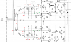
I measured the test points TP101 and TP102, which is where it gets interesting. TP101 has around 30.5v, whereas TP102 has 0! This has made me think it's something to do with the left channel, however, I am getting some really weird readings when I measure other voltages which should be the same if the schematic is to be believed.
For example, TP102 has 0v, but the legs of C104, Collector of Q132 and R116 all have ~31v even though they are all connected in parallel! How can this be? TP101 does not have this anomaly though as they are all at around 30.5v.
Secondly, on the attached diagram a similar thing occurs with R121 and R122 (marked in green). They have 36v on one side, 0 on the other but then the next resistor has 30v...
Perhaps the PCB is broken or a track shorting?
Thirdly, the bridge between the bases of Q132 and Q131 is reading 4.4v, where it should be -14.1. This leads to the CB102 connector and Q305, which is tied the the FMUTE pin on the IC. As I have 0v on this pin, Q305 is pulled high to 5.1 and subsequently delivering 4.4 volts to the bases of Q132 and Q131, which puts the amplifier in "Mute mode". I guess normally this is what happens then after the amplifier has checked PROTEC it will unmute the amp and drive the outputs? Could it be because of this (the amplifier 'muted') why I am getting weird measurements? I doesn't really explain where this leaking 30ish volts is coming from though. I have been tempted to desolder R329 to disconnect this muting operation as it would supply the correct -14.1 to Q132 and Q131... thoughts on this?
It seems the problem is common the both channels, which is annoying as it's hard to cross reference. It might be worth noting that R109 and R110 have the correct 14.5v on one side, but have 17v (instead of 0.6) on the other, which to me sounds like a shorted C121 and C122, thoughts?
Thanks HEAPS again for your help! =)
Felix
Been having another look at this and trying to trace back as far as I can where all these high voltages are coming from! It seems all the transistors should have around -1 to 1 voltages on the bases and ALL seem to be taking 30-40v....
I measured the test points TP101 and TP102, which is where it gets interesting. TP101 has around 30.5v, whereas TP102 has 0! This has made me think it's something to do with the left channel, however, I am getting some really weird readings when I measure other voltages which should be the same if the schematic is to be believed.
For example, TP102 has 0v, but the legs of C104, Collector of Q132 and R116 all have ~31v even though they are all connected in parallel! How can this be? TP101 does not have this anomaly though as they are all at around 30.5v.
Secondly, on the attached diagram a similar thing occurs with R121 and R122 (marked in green). They have 36v on one side, 0 on the other but then the next resistor has 30v...
Perhaps the PCB is broken or a track shorting?
Thirdly, the bridge between the bases of Q132 and Q131 is reading 4.4v, where it should be -14.1. This leads to the CB102 connector and Q305, which is tied the the FMUTE pin on the IC. As I have 0v on this pin, Q305 is pulled high to 5.1 and subsequently delivering 4.4 volts to the bases of Q132 and Q131, which puts the amplifier in "Mute mode". I guess normally this is what happens then after the amplifier has checked PROTEC it will unmute the amp and drive the outputs? Could it be because of this (the amplifier 'muted') why I am getting weird measurements? I doesn't really explain where this leaking 30ish volts is coming from though. I have been tempted to desolder R329 to disconnect this muting operation as it would supply the correct -14.1 to Q132 and Q131... thoughts on this?
It seems the problem is common the both channels, which is annoying as it's hard to cross reference. It might be worth noting that R109 and R110 have the correct 14.5v on one side, but have 17v (instead of 0.6) on the other, which to me sounds like a shorted C121 and C122, thoughts?
Thanks HEAPS again for your help! =)
Felix
Attachments
Last edited:
Hi Tauro,
I just went and re-measured each of the resistors and I have a 36v (or -36v if I reverse the leads) drop across both of them, meaning that I am getting a clean contact. It's hard to test them in circuit, would it be worthwhile de-soldering them and making sure they haven't gone open circuit, or is this voltage drop to be expected?
Cheers!
I'm looking... and looking - your voltage readings are not exactly nonsensical but not far short.
Initial thoughts:-
TP101 and TP102 are connected together - not sure why Yamaha would do that, doesn't seem right.
You can't have 2 vastly different voltages on the same track, i.e. left of R101 and also R102, unless that track is open circuit. In fact, there's 3 different voltages on that line.
Perhaps the schematic has errors though.
The 2.5v across C121 is also across R153 (330R) which just means there's 7.5mA going through R153. C121 can't be s/c.
I would be looking at those tracks where you have 3 different voltages again, around R121 and R122. Power down and just measure ohms for s/c between what should be connected points in the circuit, I reckon something is o/c and perhaps it's repeated across the 2 channels if it's a weak point. Are there via holes? They can go o/c.
There is another possibility though, one or both amps are oscillating at HF, you'll get all sorts of strange DVM readings if that's the case.
Last edited:
Hey guys,
Did a fair bit of probing and circuit tracking and it turns out the schematic is fairly wrong!
Here goes for an explanation, if you like I can do you up a new schematic...
1. Turns out that the left hand side of R121, R122 and TP102 are connected to 0v, hence the weird measurements.
This means that there is no connection between (R115 & R121), (R116 & R122), (TP102 & C104).
2. TP101 is correct, it connects in parallel to R101, R102, R115, R115, C103, C104, C127, Q131, Q132, CB101.
3. C127 in series with R162 connects to ground as expected.
4. The right hand sides of R121 and R122 connect as expected from the diagram.
Besides that I think everything is correct...
Having a think now, I am measuring all this without CB101 or the Rear Power Amp connected as I didn't want to introduce any input to the system? This shouldn't be a problem?
Regarding the different voltages I had on the tracks of R101 and R102, it's highly likely that this is due to my poor measurement techniques. It's hard to get a good reading when the unit only stays on for 3 seconds! When I fired it back up this morning I was only measuring ~25v on the TP101/R101/R102 etc track, however after the amp powering up and back off again enough times this slowly rose back up to around the ~31v mark. I assume this is something to do with some large cap's charging, should we think anything of this?
There are no Via Holes on this board, it's a nice and simple single layer PCB =)
Regarding the HF oscillations how likely is this? I have a DSO so I could have a look for some HF action. Would it be fine to connect this to some of the components? I have only normally used it for 9v/low current stuff and would hate to blow it up ha!
I guess the real question is where to from here? Does this incorrect schematic mean anything? It doesn't explain where this stray high voltage is coming from. Perhaps I should continue tracking back from each of the 47V rails on both channels and see what I can find?
Sorry for the long post, thanks for the help!
Cheers,
Felix
Hi,
I think you should go back to post #12 and work backward. You post that the voltage reading for the base of Q130 it is 37 volts and it should read .5 volts. This will force a high output voltage to the speaker. I would check the voltage at the base of Q110 and Q112 and both emitters.
I think you should go back to post #12 and work backward. You post that the voltage reading for the base of Q130 it is 37 volts and it should read .5 volts. This will force a high output voltage to the speaker. I would check the voltage at the base of Q110 and Q112 and both emitters.
- Status
- This old topic is closed. If you want to reopen this topic, contact a moderator using the "Report Post" button.
- Home
- Amplifiers
- Solid State
- Yamaha RX-V390 - Circuit Protection