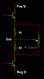
Here's an idea i've had that "might" enable better matching between Output devices.
I've shown NPN & PNP bipolar types, but these could be any others, such as MosFet etc etc, & also the same sex as in Quasi OPS's.
R1 & R2 are usually 0.1R - 0.47R 3W - 5W power resistors, or similar, but could be higher power, & normally of identical values. The variable resistor would be a power type, most likely wirewound, & suitably rated. For eg, 5W - 10W. This would be varied from its center point until an optimum position was found that better matched the OP devices. This could be left in place, or substituted with derived values, if available !
I havn't tried, or simmed it yet, due to other commitments. It looks like it "might" work as envisaged anyway ?
Thoughts etc")
I've shown NPN & PNP bipolar types, but these could be any others, such as MosFet etc etc, & also the same sex as in Quasi OPS's.
R1 & R2 are usually 0.1R - 0.47R 3W - 5W power resistors, or similar, but could be higher power, & normally of identical values. The variable resistor would be a power type, most likely wirewound, & suitably rated. For eg, 5W - 10W. This would be varied from its center point until an optimum position was found that better matched the OP devices. This could be left in place, or substituted with derived values, if available !
I havn't tried, or simmed it yet, due to other commitments. It looks like it "might" work as envisaged anyway ?
Thoughts etc
Attachments
I don't think you can talk about an 'Ron' with bipolars. My question was more like: do you want to match the gain of the two halves (the Re gives negative feedback so by adjusting Re you might be able to adjust the relative gains of the emitter followers). But I don't know if that will work. Or did you want to match the bias voltage across the Re's, for some reason?
Generally one would have a specific matching goal, and then you find a circuit idea that gives that particular goal.
Jan
Generally one would have a specific matching goal, and then you find a circuit idea that gives that particular goal.
Jan
Hi.
Probably not, it was just my way of describing things, as my idea was meant to hopefully apply to all types of output devices, not just bipolars.
Yes that was the general idea. Ahh well, if it won't work, it was worth a shot anyway. It stop me thinking about different ways of doing things etc etc though
I don't think you can talk about an 'Ron' with bipolars.
Probably not, it was just my way of describing things, as my idea was meant to hopefully apply to all types of output devices, not just bipolars.
My question was more like: do you want to match the gain of the two halves (the Re gives negative feedback so by adjusting Re you might be able to adjust the relative gains of the emitter followers)
Yes that was the general idea. Ahh well, if it won't work, it was worth a shot anyway. It stop me thinking about different ways of doing things etc etc though
I think you will be intrigued by the results when you simulate this idea. The simulator lets you plot the upper device and the lower device on the same graph (possibly using waveform arithmetic to multiply one of them by -1 if desired), and directly view the effects of potentiometer wiper-position upon "matching", however you care to define it.
If this idea works shockingly well, you might consider making a jaw-dropping demonstration of its efficacy, as follows: Apply it to a pair of devices which are deliberately chosen to be wildly unmatched. Perhaps a D45H11 PNP (fT = 70 MHz) and a MJ802 NPN (fT = 2 MHz) would shock and surprise even the most skeptical onlookers??
If this idea works shockingly well, you might consider making a jaw-dropping demonstration of its efficacy, as follows: Apply it to a pair of devices which are deliberately chosen to be wildly unmatched. Perhaps a D45H11 PNP (fT = 70 MHz) and a MJ802 NPN (fT = 2 MHz) would shock and surprise even the most skeptical onlookers??
Last edited:
@ Mark Johnson
Hi, thanks for the encouragement etc My version of Multisim is an earlier one, so doesn't have the devices you mentioned ! Anyway, i'll try testing different combinations & see what transpires, & post back. I'm not sure how to do the waveform arithmetic etc though.
It sounded as if you had a go simming, did you ? If not i would appreciate it if you did Plus if anyone else would care to, the more the merryier
Hi, thanks for the encouragement etc
My version of Multisim is an earlier one, so doesn't have the devices you mentioned ! Anyway, i'll try testing different combinations & see what transpires, & post back. I'm not sure how to do the waveform arithmetic etc though.It sounded as if you had a go simming, did you ? If not i would appreciate it if you did
Plus if anyone else would care to, the more the merryier I suspect the tolerance of the typical Re's and their thermal coef would negate any attempt to balance them. Transistors are only sort of linear in the thermal coefficient, so if you did get it all perfectly matched up on the bench, once in an amp it would be off. Just my WAG. Should be easy to set up on the bench and find out. Again, my WAG, this is probably way outside what you could study in Spice unless you made your own models. Go for it.
tvrgeek
I suspect the tolerance of the typical Re's and their thermal coef would negate any attempt to balance them.
You might be right ! Thanks for your input though
sreten
For typical output devices I cannot see what you are trying to
achieve,
Try to see if it's possible to balance Re/Ron etc between devices. As most of us know, so called complementary types are not equal in many ways, especially Re/Ron. If it is possible to do this in some way, the output should be more linear ! If my idea doesn't help to achieve this, @ least it was an honest attempt to do so, which i'm not aware of being mentioned etc before. Better to discuss etc ideas that "might" have potential, than not. As far as i'm concerned anyway !
or why you have drawn an output that cannot work.
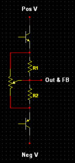
If you mean as below ? Why didn't you just say ?
vzaichenko
Am I the only one who noticed that pnp transistor is actually upside down?
LOL. You're quite right, my bad. Thanks for pointing it out
Corrected screenie posted
Attachments
- Status
- This old topic is closed. If you want to reopen this topic, contact a moderator using the "Report Post" button.
- Home
- Amplifiers
- Solid State
- Linearising OPS