Payment sent for 2 boards. Looking forward to this fine amp.... Thx for taking on this group buy....
Payment received and the package has been dropped at the post office while I was getting quotes for the others. Thanks.
If there is continued demand I would do so. I would consider getting a larger quantity next time to make it more worth while.
If you do another GB i would take 2 boards.
")
Sneek Peek
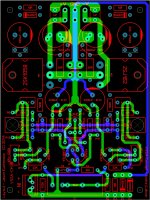
Just a snapshot to give an idea of where I'm headed. Nowhere near complete and the mark-up is a mess, so don't hang me out on the house keeping, but any general comments at this point?
Looking to move the MOSFETs up a little for better heat sink utilization and make room for a low current CM on-board to feed the front end and the VAS. Also added extra pitches for input capacitor and input connector choices. Relocated the power connections and will have room for terminal blocks or spades.
Generally I'm looking to make things more generic and adaptable. It won't be everything to everyone, but I'm sure gonna try to make it so.
Just a snapshot to give an idea of where I'm headed. Nowhere near complete and the mark-up is a mess, so don't hang me out on the house keeping, but any general comments at this point?
Looking to move the MOSFETs up a little for better heat sink utilization and make room for a low current CM on-board to feed the front end and the VAS. Also added extra pitches for input capacitor and input connector choices. Relocated the power connections and will have room for terminal blocks or spades.
Generally I'm looking to make things more generic and adaptable. It won't be everything to everyone, but I'm sure gonna try to make it so
.Attachments
A revision 'C' for the current circuit...
Folks,
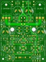
Without making any changes to the current circuit I'd like to post a possible revision to the board. Same dimensions, just added / modified the following:
Input connector pitch options added - 0.100" (2.5mm) and 0.200" (5mm).
Input capacitor pitch options added - 0.200" (5mm), 0.300" (7.5mm), 0.600" (15mm) and 0.900" (22.5mm).
Moved main PSU decoupling inward and spade connectors outward for accessibility. Minor changes to trace routing in a couple of places, nothing significant.
I'm thinking with a little massaging I would do a new, more significant order and start a dedicated thread for distribution. The response to the first two orders was fantastic (frankly I was really surprised) and I'd like to be able to offer this to more interested people. That said, I'd like to keep the thread more clear for discussion of the layout and circuit and less static pertaining to board distribution.
Feel free to comment. I'm looking to encourage active discussion, I'm no expert so I'm open to suggestions to make improvements. I am still working to wards an integrated low current CM but have been busy with other things recently, so my progress has been slow.
Folks,
Without making any changes to the current circuit I'd like to post a possible revision to the board. Same dimensions, just added / modified the following:
Input connector pitch options added - 0.100" (2.5mm) and 0.200" (5mm).
Input capacitor pitch options added - 0.200" (5mm), 0.300" (7.5mm), 0.600" (15mm) and 0.900" (22.5mm).
Moved main PSU decoupling inward and spade connectors outward for accessibility. Minor changes to trace routing in a couple of places, nothing significant.
I'm thinking with a little massaging I would do a new, more significant order and start a dedicated thread for distribution. The response to the first two orders was fantastic (frankly I was really surprised) and I'd like to be able to offer this to more interested people. That said, I'd like to keep the thread more clear for discussion of the layout and circuit and less static pertaining to board distribution.
Feel free to comment. I'm looking to encourage active discussion, I'm no expert so I'm open to suggestions to make improvements. I am still working to wards an integrated low current CM but have been busy with other things recently, so my progress has been slow.
Attachments
Hey J ....
From the 'dark side" , your layout looks superb.
The circuit is (almost ) fine....
"the cat" says 2 Q CCS's are too thermally responsive . Correct.
With a "blameless' and it's TWO 2Q CCS's (LTP and VAS) ....
they cancel each other out.
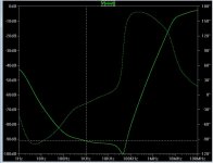
With the VSSA topology ... nothing offsets the 2Q CCS's thermal curve.
That is why I "backed off" on the 2Q and went back to the LED CCS.
Thermal simulation confirmed my suspicions .
The Hawksford VAS offset the 2Q ...to a point , but not enough.
There is another way to PSRR "heaven".
red LED CCS + R/C at the VAS Re !!
Decouple the VAS Re with 220u/33R and 90db+ PSRR you will have...
(as yoda says).
PS - for the CCS's ... run one with a fixed R , the other with a smaller R + the trimmer... one less trimmer.
OS
From the 'dark side" , your layout looks superb.
The circuit is (almost ) fine....
"the cat" says 2 Q CCS's are too thermally responsive . Correct.
With a "blameless' and it's TWO 2Q CCS's (LTP and VAS) ....
they cancel each other out.
With the VSSA topology ... nothing offsets the 2Q CCS's thermal curve.
That is why I "backed off" on the 2Q and went back to the LED CCS.
Thermal simulation confirmed my suspicions .
The Hawksford VAS offset the 2Q ...to a point , but not enough.
There is another way to PSRR "heaven".
red LED CCS + R/C at the VAS Re !!
Decouple the VAS Re with 220u/33R and 90db+ PSRR you will have...
(as yoda says)
.PS - for the CCS's ... run one with a fixed R , the other with a smaller R + the trimmer... one less trimmer.
OS
Attachments
Hey J ....
From the 'dark side" , your layout looks superb.
The circuit is (almost ) fine....
There is another way to PSRR "heaven".
red LED CCS + R/C at the VAS Re !!
Decouple the VAS Re with 220u/33R and 90db+ PSRR you will have...
(as yoda says)
PS - for the CCS's ... run one with a fixed R , the other with a smaller R + the trimmer... one less trimmer.
OS
Thanks much for the input 'Uncle OS'. I'm quite humbled that you suggest my layout looks good
. I have been trying to learn a few lessons.On these boards you can do either a 2Q CCS or a 1Q+LED CCS without modification of the board, just sub the BC550 and BC560 transistors with LEDs connected across the C-E pads (mind the polarity of course) and change the 22K resistors for something more like 3K3 to 3K9 to properly bias the LEDs. Sheldon built his this way.
The two trimmers for the CCSs provides the option of 'tuning' the VAS current and offset at the output, something one gives up if one side fixed.
Now, I saw the VAS R-C trick in your VSSA IPS for the Slew series and you can consider my interest piqued! Something to have a look at...
Thanks much for the input 'Uncle OS'. I'm quite humbled that you suggest my layout looks good
On these boards you can do either a 2Q CCS or a 1Q+LED CCS without modification of the board, just sub the BC550 and BC560 transistors with LEDs connected across the C-E pads (mind the polarity of course) and change the 22K resistors for something more like 3K3 to 3K9 to properly bias the LEDs. Sheldon built his this way.
The two trimmers for the CCSs provides the option of 'tuning' the VAS current and offset at the output, something one gives up if one side fixed.
Now, I saw the VAS R-C trick in your VSSA IPS for the Slew series and you can consider my interest piqued! Something to have a look at...
You might influence me,yet...
2 trimmers will allow for global VAS I control as well as offset.
I was being "cheep" ... forgive me.
OS
On My first VSSA, Jason's TO-3 design, I mounted both boards on one heatsink that is 4 1/2' x 11" with 1" fins running horizontally and it does just fine. I'm not saying this is the best orientation, just letting you know that these amps don't run all that hot. BTW that amp may still be my favorite of the 4 VSSA I've built.
" BTW that amp may still be my favorite of the 4 VSSA I've built"
Hi Terry ,i can't understand what you mean.
What is BTW?
Thimios.
" BTW that amp may still be my favorite of the 4 VSSA I've built"
Hi Terry ,i can't understand what you mean.
What is BTW?
Thimios.
BTW = By The Way
Any advantage/disadvantage to swapping out the the BC550/560 for the diodes? I haven't installed it in a case yet.
I'm going to suggest leaving it as is. Converting the CCS requires changing out the two transistors for LEDs, changing two fixed resistor values and changing the two trimmers for new values. I think since the board is all plated holes the difficulties or risk of damaging the board does not outweigh any advantage gained. The only real downside of the 2Q in this application is a little drift in bias of the input and VAS with temperature.
Next circuit revision will likely see two CCS options, JFET and 1Q+LED.
New thread started in Group Buys:
http://www.diyaudio.com/forums/group-buys/251782-vssa-through-hole-version-jason.html#post3831506
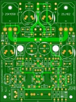
A new batch of revision 'C' boards has been ordered, expecting delivery in about two weeks. Same circuit, slight modification of the PCB as above.
http://www.diyaudio.com/forums/group-buys/251782-vssa-through-hole-version-jason.html#post3831506
A new batch of revision 'C' boards has been ordered, expecting delivery in about two weeks. Same circuit, slight modification of the PCB as above.
I have a dh220 shell and a dh200 shell both with good hitachi"s on them. short leads down to the mosfets should not be a problem they are hooked up that way in the existing unit. These both have a lower voltage torroid mounted instead of the factory iron as well. A flat shelf is no prob I have a machined ALU platform mounted there as well.
- Status
- This old topic is closed. If you want to reopen this topic, contact a moderator using the "Report Post" button.
- Home
- Amplifiers
- Solid State
- VSSA Through-Hole Version by Jason