Translating this with Google.
Another Crescendo construction, it is the third I solder together with my children. This is the Millenium version, where I can not get the idle current law. I have a little over 200mV on both channels :-(, where it should be about 44-55mv. Trim pot is counter-clockwise as much as possible. Has checked all the transistors and they sit right.'ve Also checked all the resistance and it is right also. Could it be that the power transistors are poorly adapted (matched). Bought them on Ebay. Considering now on raising the trim pot to about 2-5K if it helps or should you raise something fixed resistor instead of, for example: R28. Dislike raising trim pot, but what do you suggest me to start with. buying new power transistors, yes it will be a bit more expensive than what I had in mind from the beginning.
Janne Sweden!
I think I found my problem here, there were many pages before I found the answer.
Thank you!
http://www.diyaudio.com/forums/solid-state/174783-crescendo-millennium-offset-problem-28.html
Thank you!
http://www.diyaudio.com/forums/solid-state/174783-crescendo-millennium-offset-problem-28.html
Now, I was tired, did not help this fix. Come down any mv to about 150/200mv, I give up this weekend, there are a few times now that you have removed all connections to remove the circuit boards. Neither do I believe that I can do as much or more? I myself think it is the final transistors I need to change? This 2SK537 I have a couple more of, so these we change again. Fiddling Amplifier.
There is current flow in the output transistors that I have trouble with. The speaker outputs, it is not much volts to tell about 0.05 or so.
It would not be lower than about 200mV, where it should be 44-55mv. So it gets really hot fast.
I have built one exactly the same for about 4 years ago, where one channel went just
to get down to the maximum quiescent current under Elektor, while the other channel had a good span of potensiometern, where the quiescent current was no problem to set.
Attachments
Well there could be two things wrong.
1) A straightforward bias issue
2) Instability where the amp is oscillating. That would really need a scope to check.
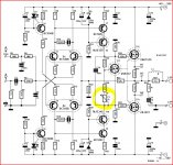
For DC bias (assuming no instability) then lowering the value of the resistor chain of P1 and R28 will lower the bias. You could even apply a short across C10 as a test. The bias current should drop to zero in that case. I would try lowering R28 first to perhaps 47 ohm and see if sets up then.
Are the FET's the specified type ? as turn on voltages vary between different devices.
1) A straightforward bias issue
2) Instability where the amp is oscillating. That would really need a scope to check.
For DC bias (assuming no instability) then lowering the value of the resistor chain of P1 and R28 will lower the bias. You could even apply a short across C10 as a test. The bias current should drop to zero in that case. I would try lowering R28 first to perhaps 47 ohm and see if sets up then.
Are the FET's the specified type ? as turn on voltages vary between different devices.
Feels a bit like you want to be kidding me. To me it feels like R28 needs to be raised instead. Jumpering C10, if you are right for it, you should have, I can test with a variable resistor across, or over R28 to lower the resistance, to avoid having to remove the board every time you try something new. Removed the final FETs tonight as it was short-circuited two legs on a 2sk1530. I have ordered 4 new FETs of each, will by the end of the week. Otherwise, I have looked through all the resistors, capacitors, diodes and transistors, then with a multimeter and can not find more errors. Thanks so far.
Janne Oland
Janne Oland
Janne, I'm sorry, I've given you some misleading info. Yes, you can short out C10 to force the bias to zero but you are correct, R28 and the pot need to be raised in value to achieve the same reduction. For some reason I looked and didn't see the third FET as a Vgs multiplier. No excuses for that ")
You can remove R28 and that should have the same effect as shorting C10. The bias should fall to zero.
You can remove R28 and that should have the same effect as shorting C10. The bias should fall to zero.
I recieved my new power transistors today, but did not help it to get lower quiescent current. 've Checked all my components for the third time, but they're right.
Have also replaced some transistors that I had more of. Do not get this, I'll check out a similar amp that I built with my oldest son for about 3-4 years ago, if I changed the value of some resistors or so. Now, I am no longer with this hassle amplifiers. I need help if someone has the desire. voltage is about 200mV, then it must be about 50mV across R34 or R35.
Have also replaced some transistors that I had more of. Do not get this, I'll check out a similar amp that I built with my oldest son for about 3-4 years ago, if I changed the value of some resistors or so. Now, I am no longer with this hassle amplifiers. I need help if someone has the desire. voltage is about 200mV, then it must be about 50mV across R34 or R35.
- Status
- This old topic is closed. If you want to reopen this topic, contact a moderator using the "Report Post" button.
- Home
- Amplifiers
- Solid State
- Crescendo Millenium problems