Hi guys!
Im pretty new in audio and I could use some help!
Well I got an not working Technics SU V40 amp and decided to repair it. I know many of you will say it is not worth trying and it makes more sense to implant new amp in there but that is the last optio I will do if everything else fails.
OK so I got this amp second hand, it got a piece of wire instead of fuse in it so I replaced that first and powered it up. As expected, nothing happens. Amp stays in protection, no relay click. So I tested voltages and it appears that all are good. I got solid +-47V and +-15 for preamp. Then I checked for shorted transistors, but all of them seem to be ok. I then replaced all electrolythic caps in it except the two big filter ones. Still, no difference. As many people say, these amps failed often because the big SVI chip failed. So, I checked this too, soldered it out of the pcb and measure for shorts. It appears that only pins 4 and 5 are shorted and also pins 20 and 21. This is where I need you guys! Can somebody tell me if this chip is busted or not? I couldnt find any datasheet for it.
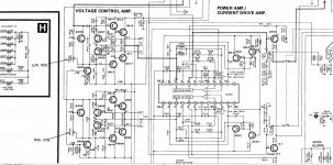
One thing that tells me it may be ok is that I measured a few voltages around without the chip installed and it appears that I have -39V in the middle of voltage control amp - on test points TP1 and TP2, both chanells the same (see schematic - it is not for V40 but for V50 which is almost identical). Also I got -39V on diodes D501 and 502 instead of 6.3V.
I am confused and cant find where this thing is leaking. I tested all transistors in voltage c. amp and all apears to be ok. Can anyone help me which component to look for, or should I go and replace everything including ceramic caps and resistors?
Thanks for any help!
Greg
Im pretty new in audio and I could use some help!
Well I got an not working Technics SU V40 amp and decided to repair it. I know many of you will say it is not worth trying and it makes more sense to implant new amp in there but that is the last optio I will do if everything else fails.
OK so I got this amp second hand, it got a piece of wire
instead of fuse in it so I replaced that first and powered it up. As expected, nothing happens. Amp stays in protection, no relay click. So I tested voltages and it appears that all are good. I got solid +-47V and +-15 for preamp. Then I checked for shorted transistors, but all of them seem to be ok. I then replaced all electrolythic caps in it except the two big filter ones. Still, no difference. As many people say, these amps failed often because the big SVI chip failed. So, I checked this too, soldered it out of the pcb and measure for shorts. It appears that only pins 4 and 5 are shorted and also pins 20 and 21. This is where I need you guys! Can somebody tell me if this chip is busted or not? I couldnt find any datasheet for it. One thing that tells me it may be ok is that I measured a few voltages around without the chip installed and it appears that I have -39V in the middle of voltage control amp - on test points TP1 and TP2, both chanells the same (see schematic - it is not for V40 but for V50 which is almost identical). Also I got -39V on diodes D501 and 502 instead of 6.3V.
I am confused and cant find where this thing is leaking. I tested all transistors in voltage c. amp and all apears to be ok. Can anyone help me which component to look for, or should I go and replace everything including ceramic caps and resistors?
Thanks for any help!
Greg
SUV series are difficult to understand in operation, let alone find unobtanium parts for. They began close to the class S design (SEA series) but developed through SUV, SUZ to something else again. Unless you have access to genuine spares, specific to the model, the chances of repairing it are slim unless you are skilled and have model-specific service notes.
You can be sure though, that if you measure near rail voltage at the centre (output?) of the power module(s), the amplifier module has failed with 1 or more shorted transitors.
I have an SUV50 model and would much appreciate more of the schematic than the thumbnail view. Could you post a link or email if the full schematic is available?
Thanks for your input, Ian. Yeah, I see that this technics amps have everything but usual layouts.. Anyway I like the challenge so I wont give up that easy
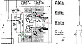
I will give it another look when I come home. One thing that bugs me is that I have same voltages on both channels. Coincidence? I did remove Q403, 409, 413 and their oposites on the other channel but the problem is still there. SU V40 doesnt have Q405 and 406 transistors but has resistors instead. I did check the Q417 and 418 with multimeter and they seem ok but I will remove them from circuit to be sure and report.
I will give it another look when I come home. One thing that bugs me is that I have same voltages on both channels. Coincidence? I did remove Q403, 409, 413 and their oposites on the other channel but the problem is still there. SU V40 doesnt have Q405 and 406 transistors but has resistors instead. I did check the Q417 and 418 with multimeter and they seem ok but I will remove them from circuit to be sure and report.
OK, I understand your desire to repair but consider: a fuse has blown and at least one channel won't work so the repairer fitted wire and powered up again - still doesn't work. So, no faults or is something actually burned out? Fuses need a lot of fault current to blow when there is a speaker protection circuit as well and that can only be from a high current source facing a near short to ground. With no other signs of failure, that means the power amplifier is the short.
You can almost bet the power amp is burned out in one channel at least and protection circuits sense DC as a result, so it won't connect the DC to your speakers and rightly so. As it's now too late to prevent further damage, measure the voltages to the power supply ground from pins 5, 20 on the power IC - in circuit. If you measure more than a volt at those output pins, start thinking about your next project.
You can almost bet the power amp is burned out in one channel at least and protection circuits sense DC as a result, so it won't connect the DC to your speakers and rightly so. As it's now too late to prevent further damage, measure the voltages to the power supply ground from pins 5, 20 on the power IC - in circuit. If you measure more than a volt at those output pins, start thinking about your next project.
Last edited:
Sorry for bringing this one up again but I havent given up on this amp yet
I spent a bit more time investigating the pcb and found out a few things:
The SVI IC appears to be OK, since I removed it from the circuit and amp was still in protection. I then removed jumpers which connect voltage amp section with the current amp section and protection went off. So that tells me that fault is somewhere in voltage amp part.
I did some measurements again and as previus I get - supply voltage almost everywhere in that part (see attached schematic). I removed all transistors and test them and all are just fine. I then removed resistor marked green and all negative voltages dissapeared. I then replaced this resistor and some others nearby but problem is still there.
What could be causing this state? What should I look for?
Any help is much appreciated!
Attachments
Have you measured voltages at pins 5,20 yet? You may have the voltage and class A amplifiers working without the current output stage but that may have little to do with giving the correct result when coupled.
The section you show is the class A amplifier which also drives the output via a resistance in a bridge type circuit, This is effectively a class S design, so the class A amp is only a reference, an error is generated by it trying to drive the low impedance speakers. This is sampled and used to drive the hybrid class B power module (as a current-dumper) in an error correction mode. The bridge circuit though, is inside the large IC, so difficult to follow. The annoying part is that unless you have the bridge in the circuit with its DC stabilizer circuits, the amplifier cannot function. i.e. IC402 must be working.
This is not easy to understand without a block diagram. The only one I have seen is a very basic form in one of JLH's articles in WW magazine and his book "Audio Electronics."
I suggest you read up what you can find on class S and even the somewhat similar Quad 405, 306,606 etc. designs before looking in the wrong places. It's not a straightforward amplifier by any stretch of the imagination
- Status
- This old topic is closed. If you want to reopen this topic, contact a moderator using the "Report Post" button.
- Home
- Amplifiers
- Solid State
- Technics SU V40 repair