I bought a GFA-555 II amp last night for one and half centuries.
Seller said it was installed in a church and they upgraded system.
Anywho, I checked DC at the speaker terminals and it is 1.4 and 1.44 constant without anything connected.
When speakers are connected without input, it's around 0.03.
I connected pre-amp and there is no output from the speakers.
Checked the fuse and the leftmost fuse is blown. Other fuses are okay.
It has AGC-7A/250V label on the fuse.
Should I get fast blow or slow blow fuse?

If it's something else, should I return it and get money back or have it fixed professionally?
Thanks for information.
Seller said it was installed in a church and they upgraded system.
Anywho, I checked DC at the speaker terminals and it is 1.4 and 1.44 constant without anything connected.
When speakers are connected without input, it's around 0.03.
I connected pre-amp and there is no output from the speakers.
Checked the fuse and the leftmost fuse is blown. Other fuses are okay.
It has AGC-7A/250V label on the fuse.
Should I get fast blow or slow blow fuse?
If it's something else, should I return it and get money back or have it fixed professionally?
Thanks for information.
Get an AGC 7A fuse.. (a fast acting type)  Seriously I would return it and get your money back, out of the box not working is not a good starting point if it was represented as being in working order. Repairs will be expensive.
https://www.egr.msu.edu/eceshop/Parts_Inventory/datasheets/10ma 3AG Fuse.pdf
Seriously I would return it and get your money back, out of the box not working is not a good starting point if it was represented as being in working order. Repairs will be expensive.https://www.egr.msu.edu/eceshop/Parts_Inventory/datasheets/10ma 3AG Fuse.pdf
Okay found matching fuses@ radioshack.
m.radioshack.com/radioshack/product/detail.do?itemId=2103755&op=%22http://www.radioshack.com/product/index.jsp?productId=2103755%22
7.0A 250V Fast-Acting 1¼x¼" Glass Fuse (4-Pack)
Catalog #: 270-1013 | Model: 27-1013
I'll try tonight and update.
m.radioshack.com/radioshack/product/detail.do?itemId=2103755&op=%22http://www.radioshack.com/product/index.jsp?productId=2103755%22
7.0A 250V Fast-Acting 1¼x¼" Glass Fuse (4-Pack)
Catalog #: 270-1013 | Model: 27-1013
I'll try tonight and update.
Another question.
I adjusted BIAS pots and measured speaker terminals.
I could not find the terminal points in service manual to measure BIAS so just went with speaker terminals.
I marked the location before changing and adjusted it back to original.
It may be off slightly but should be close.
From service manual:
Is there a better diagram that shows where to check bias and how to adjust DC offset?
Also, how do I get 66 watts with input?
Thanks for info.
I adjusted BIAS pots and measured speaker terminals.
I could not find the terminal points in service manual to measure BIAS so just went with speaker terminals.
I marked the location before changing and adjusted it back to original.
It may be off slightly but should be close.
From service manual:
Service manual doesn't show where the TP201, TP301, TP251 and TP351 are.1. set bias controls (R119 and R169) to midpoint.
2. Connect a millivolt meter across TP201 and TP301.
3. Turn amplifier on and allow 3 to 5 minute settling period.
4. Adjust BIAS control R119 to obtain either a + or - 10mV(+-1mV) indication on the millivolt meter.
5. Connect a millivolt meter across TP251 and TP351.
6. Adjust BIAS control R169 to obtain either a + or - 10mV(+-1mV) indication on the millivolt meter.
7. To check for proper bias setting, remove millivolt meter and appy input signal to obtain 66 watts into 8 ohms for 10 minutes with cover on.
8. Remove input signal and connect the millivolt meter as in Step 2 and step 5. Let amplifier idle until bias stabilizes and readjust to 10mV(+-1mV).
Is there a better diagram that shows where to check bias and how to adjust DC offset?
Also, how do I get 66 watts with input?
Thanks for info.
This has become confusing.
After you replace the fuse check the DC voltage out on each channel. Use a power resistor (not a speaker) as the load (a 10 watt 10 Ohm resistor will only cost a dollar at radio shack). If you then measure 1.4 volts DC then DO NOT hook up a speaker to the amp. There could be a number of possibilities. None of them would be simple or cheap.
After you replace the fuse check the DC voltage out on each channel. Use a power resistor (not a speaker) as the load (a 10 watt 10 Ohm resistor will only cost a dollar at radio shack). If you then measure 1.4 volts DC then DO NOT hook up a speaker to the amp. There could be a number of possibilities. None of them would be simple or cheap.
This has become confusing.
After you replace the fuse check the DC voltage out on each channel. Use a power resistor (not a speaker) as the load (a 10 watt 10 Ohm resistor will only cost a dollar at radio shack). If you then measure 1.4 volts DC then DO NOT hook up a speaker to the amp. There could be a number of possibilities. None of them would be simple or cheap.
Okay will get the resistor.
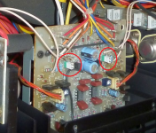
Now back to the test points.
Are these highlighted in red the test points?
If yes, do I test on two pins of the same part or across?
Thanks
Attachments
NO
The test points you identified are for adjusting the bias. The problem you are having (I thought) is DC at the output (the speaker jacks). There should be minimal DC voltage there (my guess is less than 20-40 mV).
Where did you measure the DC voltage you mentioned above?
The test points you identified are for adjusting the bias. The problem you are having (I thought) is DC at the output (the speaker jacks). There should be minimal DC voltage there (my guess is less than 20-40 mV).
Where did you measure the DC voltage you mentioned above?
NO
The test points you identified are for adjusting the bias. The problem you are having (I thought) is DC at the output (the speaker jacks). There should be minimal DC voltage there (my guess is less than 20-40 mV).
Where did you measure the DC voltage you mentioned above?
I measured DC voltage at the speaker terminals that showed 1.4 and 1.44 without connecting anything.
When speakers are connected, it showed 0.03 on both.
I also wanted to check the bias and make sure it has good numbers.
I think I am looking at wrong board.
May be I should look at the side vertical boards, not the board where the bias adjustment is.
Attachments
There is a procedure for measuring/adjusting the bias. It is detailed in the Adcom service manual (there are free copies if you do a Google search). You will need a voltmeter and a power resistor.
However, I would not bother with the bias until this problem about DC voltage at the output jacks is solved. Given your voltmeter, experience, etc. are you sure you are measuring 1.4 volts DC at the output jacks? Forgive me if this sounds patronizing, but we do not know your level of experience.
IOW, 1.4 volts DC is not normal.
Fuses were the issue but bias and DC are still a mystery.
Thanks for comments.
I checked all the fuses' values and it was a mix.
One was 5A which was blown, two were correct 7A (AGC 7A-250V/312) and one was 6A.
I replaced the two 5A and 6A with 7A and now it is working fine.
BTW, I found the test points. They are small metal bars on the vertical boards.
However, setting bias is so weird.
When I adjust the resistor, it changes value but automatically comes back to around zero soon after when no input is connected.
On right channel, it doesn't even do anything. Left channel changes value but resets to zero.
Then I connected input signal and played a track and bias went up and down depending upon the music, around 14 to 18mV.
So basically, can't adjust bias.
Also checked DC voltage and it was close to 0 fluctuating sometimes to .001 when speakers were hooked up so I guess it's good.
I read this amp doesn't have speaker protection so that's something to read next. May be external DC protection is the way to go.
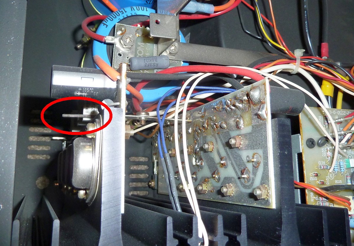
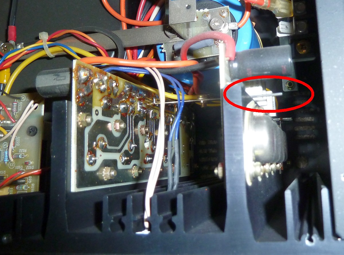
Here are the test points for reference highlighted in red circle.
However, they are not numbered TP201, TP301, TP251 and TP351 as mentioned in the service manual.
The numbers were J### something.

Thanks for comments.
I checked all the fuses' values and it was a mix.
One was 5A which was blown, two were correct 7A (AGC 7A-250V/312) and one was 6A.
I replaced the two 5A and 6A with 7A and now it is working fine.
BTW, I found the test points. They are small metal bars on the vertical boards.
However, setting bias is so weird.
When I adjust the resistor, it changes value but automatically comes back to around zero soon after when no input is connected.
On right channel, it doesn't even do anything. Left channel changes value but resets to zero.
Then I connected input signal and played a track and bias went up and down depending upon the music, around 14 to 18mV.
So basically, can't adjust bias.
Also checked DC voltage and it was close to 0 fluctuating sometimes to .001 when speakers were hooked up so I guess it's good.
I read this amp doesn't have speaker protection so that's something to read next. May be external DC protection is the way to go.
Here are the test points for reference highlighted in red circle.
However, they are not numbered TP201, TP301, TP251 and TP351 as mentioned in the service manual.
The numbers were J### something.
Attachments


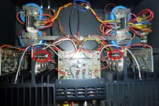
They want a sizable input signal (66 watts). Use a tone generator (or recorded tone on a CD). Dial it up using the relation: Power = Volts^2/R. "R" is the power resistor (and it will get hot). The amp must be warmed up before testing the bias. Follow those instructions carefully. Adjusting those pots will alter the bias and you should be able to read this at the test points.
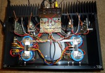
Please note that the traces on the Left and right circuit boards look different. The ones on the left look like thay have gotten very hot in their previous life (compare to the right side). That hodge podge of different fuses, suggest this amp has a bad history.
Please note that the traces on the Left and right circuit boards look different. The ones on the left look like thay have gotten very hot in their previous life (compare to the right side). That hodge podge of different fuses, suggest this amp has a bad history.
They want a sizable input signal (66 watts). Use a tone generator (or recorded tone on a CD). Dial it up using the relation: Power = Volts^2/R. "R" is the power resistor (and it will get hot). The amp must be warmed up before testing the bias. Follow those instructions carefully. Adjusting those pots will alter the bias and you should be able to read this at the test points.
Please note that the traces on the Left and right circuit boards look different. The ones on the left look like thay have gotten very hot in their previous life (compare to the right side). That hodge podge of different fuses, suggest this amp has a bad history.
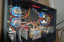
The traces are different as their arrangement is different in each channel.
The outer right board is same as the inner left board and vice versa.
Same board uses same colored wire.
This picture shows same trace on the boards.
Yes, it does look little brown on that right channel board.
I'll check what to do with bias.
I couldn't find 10w 10ohm resistor at the Radioshack but I have bunch of 25w 2.7 ohm resistors that I can use three of them in series to get around 8 ohms for testing.
Last night I used two for a total of 5.4 ohms for DC test.
It's working fine so I may leave it for now.
BTW, if I want to use external inline fuse on the + speaker terminals as this amp doesn't have DC protection, what fuse size is good?
The speakers are Boston A400's, 4 ohms 150 watts.
So 150/4 = 37.5
Square root of 37.5 = 6.12
6A fuse??? That sounds very high.

The amp has two 7A fuses on each channel.
Thanks
Attachments
So far it's running good...
I tested the amp with some test speakers for around 4 hours continuous at moderately high levels and it felt very slightly warm on both sides.
It's not even hot at all.
So I plugged in the Boston A400's and listened all day yesterday.
I have not tested the Bias but it's more or less exactly in the middle as it was before I adjusted it.
I'm guessing it may be off by few mV's in the two channels but that shouldn't hurt right?
Thanks
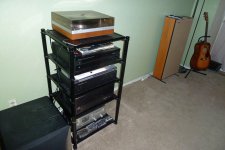
Here is the setup in my living room:
Philips 312 Turntable.
Yamaha CD Player (I have a Nakamichi CD player somewhere in the basement that'll replace it soon).
Harman Kardon Signature Series AP2500 Pre-amplifier.
Adcom GFA-555 II Amplifier.
Marantz 3000 Cassette Player.
Boston Acoustics A400 Speakers.
Definitive Technology PF15TL+ subwoofer.
I tested the amp with some test speakers for around 4 hours continuous at moderately high levels and it felt very slightly warm on both sides.
It's not even hot at all.
So I plugged in the Boston A400's and listened all day yesterday.
I have not tested the Bias but it's more or less exactly in the middle as it was before I adjusted it.
I'm guessing it may be off by few mV's in the two channels but that shouldn't hurt right?
Thanks
Here is the setup in my living room:
Philips 312 Turntable.
Yamaha CD Player (I have a Nakamichi CD player somewhere in the basement that'll replace it soon).
Harman Kardon Signature Series AP2500 Pre-amplifier.
Adcom GFA-555 II Amplifier.
Marantz 3000 Cassette Player.
Boston Acoustics A400 Speakers.
Definitive Technology PF15TL+ subwoofer.
An externally hosted image should be here but it was not working when we last tested it.
Attachments
Last edited:
Fuses are there to prevent fires, but they don't always even do that. The silicon fuses are usually quicker than the wire fuse. Speaker cones flying across the room can happen long before the fuse blows. Surprise! That's a big honking amp and it can do some damage.
Bias being low will cause lots of distortion. Being a bit high not so much. Too high can lead to stability issues. You find them easily when it sounds funny and by the time you walk over to it, the heat sink is too hot to touch and the outputs will fry when your hand is about a foot away from the power switch. This I know first hand, thank you CM Labs.
DC offset on the speaker terminals should by under 50mV or so. Things do drift with years. You may want to add some way to adjust the offset, by pot or add DC servo.
I can't remember, did the series II have one of Nelson's automatic opto-coupled bias adjustment setups? Series one used his driver current sense, but I don't know what changed.
Fuses are there to prevent fires, but they don't always even do that. The silicon fuses are usually quicker than the wire fuse. Speaker cones flying across the room can happen long before the fuse blows. Surprise! That's a big honking amp and it can do some damage.
Bias being low will cause lots of distortion. Being a bit high not so much. Too high can lead to stability issues. You find them easily when it sounds funny and by the time you walk over to it, the heat sink is too hot to touch and the outputs will fry when your hand is about a foot away from the power switch. This I know first hand, thank you CM Labs.
DC offset on the speaker terminals should by under 50mV or so. Things do drift with years. You may want to add some way to adjust the offset, by pot or add DC servo.
I can't remember, did the series II have one of Nelson's automatic opto-coupled bias adjustment setups? Series one used his driver current sense, but I don't know what changed.
I have no idea if they have automatic bias adjustment.
May be someone here can answer.
I don't have expensive speakers so main issue is fire hazard so I'll make sure to turn everything off when I'm not around them.
- Status
- This old topic is closed. If you want to reopen this topic, contact a moderator using the "Report Post" button.
- Home
- Amplifiers
- Solid State
- Adcom GFA-555 II issue...