HI
I own an fairly good and well reviewed commercial amplifier.
I'm happy with it but I know it'n not the very top of the cream...
Lately, did compare it against 2 much more expensive amplifier (both SS and fairly same RMS power) and we realized that mine was lacking in sound-stage depth vs the 3-4X more expensive ones.
Mine had very good sound and impact but the blacker background and depth where evident to notice.
We used same wire and same system, just an amp swap.
I wonder If I modify the input stage from this would help my 3D imaging.
to:
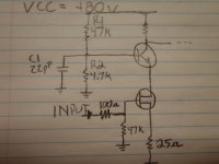
reduce R1 from 47k to 10K
replace R2 by a 9.1V zener
Parallel an 47uf or about Elna muse to C1
Also, the power supply that feed the input section is a fairly simple capacitance multiplier done with a 2sc2235
Will changing the resistor to a zener improve thing here too?
What one can do to adress specificly the soundstage on an amplifier?
thanks
I own an fairly good and well reviewed commercial amplifier.
I'm happy with it but I know it'n not the very top of the cream...
Lately, did compare it against 2 much more expensive amplifier (both SS and fairly same RMS power) and we realized that mine was lacking in sound-stage depth vs the 3-4X more expensive ones.
Mine had very good sound and impact but the blacker background and depth where evident to notice.
We used same wire and same system, just an amp swap.
I wonder If I modify the input stage from this would help my 3D imaging.
to:
reduce R1 from 47k to 10K
replace R2 by a 9.1V zener
Parallel an 47uf or about Elna muse to C1
Also, the power supply that feed the input section is a fairly simple capacitance multiplier done with a 2sc2235
Will changing the resistor to a zener improve thing here too?
What one can do to adress specificly the soundstage on an amplifier?
thanks
Attachments
Member
Joined 2009
Paid Member
I have never worked with this kind of circuit, but I would imagine, as you have, that the supply rail noise is finding it's way to the base of the cascade device. Zener diodes aren't that quiet either though - a larger C1 might reduce noise at the base of the cascade device. But the output from this stage is from the collector of the Cascode so it has plenty of power supply noise already. Maybe you can clean up the power supply to the front end with a capacitance multiplier ?
I guess you have to be careful not to move the operating point of the FET too far - it needs that cascade at a certain voltage to keep the FET within it's operating range for voltage and power dissipation.
I don't see much benefit from decreasing the 47k resistor to 10k, it really doesn't seem large enough to be a problem noise source.
I wonder If I modify the input stage from this would help my 3D imaging.
...
What one can do to adress specificly the soundstage on an amplifier?
thanks
No, not even in your wildest dreams.

...
Buy/make a new amp, possibly CFA type.

Regards, L.C.

Hi,
Can you post a full schematic of the amplifier?
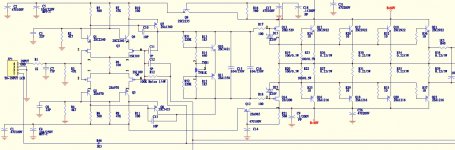
this is one whole channel.
the input bias supply and the capacitance multiplier are my area of interest.
I also think of paralleling better quality caps across C15
most power supply caps are already bypassed with silmic caps.
Attachments
Last edited:
What one can do to adress specificly the soundstage on an amplifier?
Its an excellent question - we could certainly do with more such questions here
In my experience, soundstage of an amp has to do with the amount of noise that gets amplified. A 'dynamic SNR' if you like, not the usual SNR which is measured with the input shorted to get the 'N' part; rather N in presence of S.
The noise comes from two sources - external kit (sources, loads) and the amp's own power supply.
Star earthing all the signal grounds and keeping them totally separate from power grounds and grounds going to external kit is the first step in getting a decent soundstage from an amp. So schematics aren't particularly helpful in getting at the problem - PCB layouts showing how tracks run are far superior.
Do you have a PCB layout to share?
Post models or even better even basic schematics of the amplifiers you made tests with ...You will have your answer with in seconds !!!
I may guess that the amplifiers that beat your amplifier are more simply made ...far more simply made but just a bit beefy when it comes to power supply and e few more other details ...
For a real example you must think that a designer is based on a concept which often is effected by other parameters ...One thing that is often missed is what i cal transfer characteristics :
One may be able to design a perfect LTP stage , choose to go with this type of VAS and a specific choice of semis that produce for example A result .
One thing that is very important( on a design/production level ) is to be able to transfer or "pass "" these good characteristics from the first stages of the amp to the last and eventually to the speakers .
My last guess ( i can bet also if you like ) that a DIY amplifier will have more sound stage than yours but probably less power ...Try and let us know
Input of your amplifier is just fine messing up there will not change the 3D only cause stability issues ...your problem lays elsewhere ...
Kind regards
Sakis
Last edited:
...
most power supply caps are already bypassed with silmic caps.
You should remove those, IMHO. Randomly adding "bypass" caps usually does no good.
From the schematic it appears that this is a Parasound amp, which model is it ?
You should remove those, IMHO. Randomly adding "bypass" caps usually does no good.
From the schematic it appears that this is a Parasound amp, which model is it ?
Is there a reason for it or it's just from experience?
Yes, it's a parasound, still current production but do not know if there is copyright to respect to post partial schematic, I just asked for the full schematic and got it via email...
My last guess ( i can bet also if you like ) that a DIY amplifier will have more sound stage than yours but probably less power ...Try and let us know
Yes, I build the F5 and F5turbo and soundstage was better than my amp.
I also have a hiraga 30Watts (scaled down to 25ish watts) and it also have a good soundstage.
It make me think, if the ground resistance is so important, Should I wire a plain ground on my board (maybe solid awg 16 across the negarive trace)
the trace are wide but not particulary thick.
I guess, I could drop the impedance quite a bit there...
Hint: Soundstage is not a well-defined technical property of an amplifier. It's an illusion that's created in your head. So there's the speakers, room and auditory system in between.
Before being able to "fix" anything, you first have to find out what's wrong - in technical terms. For example, there might be excessive crosstalk with speakers attached, though I'd be surprised to find a name-brand commercial amplifier containing the required stupid wiring mistakes.
My bets would be on speaker-amp interaction. Maybe your amplifier is just fine but the one you're comparing it to has only average damping factor (high output impedance). The F5, for example, is given with a DF of ~40, into 8 ohms I assume (which would mean 0.2 ohms of output impedance, an OK but hardly breathtaking value). The resulting slightly warped speaker frequency response may be sufficient to create the impression of better soundstaging.
You'd also be well-advised to make sure you're not fooling yourself, since somewhat levels alone may throw off hearing significantly, and the gain of any two different amplifiers rarely is matched to within 0.1 dB. Ideally you'd also be able to compare amplifiers directly on the same speakers by means of a suitable speaker switch (non-shorting type, low resistance) on the output. Listening tests that are (a) not level-matched and (b) sighted are problematic and easily produce distorted results.
Step ONE: Is the bias set correctly? Bet not.
Step TWO: If it is over 7 to 10 years old, has int been re-capped? Bet not.
I too don't know what yo mean by "sound stage". I would do better with other review editor abstract useless descriptions like "air" as I may be able to relate that to reality.
Ground and power. Treat them the SAME. (no buss!) There is a lot of very good tips on this. It still amazes me that after the thousands of posts, people still think ground is some magical source/sink of electrons. It is just a path.
Yes, I build the F5 and F5turbo and soundstage was better than my amp.
I also have a hiraga 30Watts (scaled down to 25ish watts) and it also have a good soundstage.
Parasound is far from the first league. Ask yourself a question what is the major difference between F5, JLH and your's?

@etalon90:
That looks like one of John Curl's designs. Why not head over to his thread and ask his opinion? (Probably best to wait for a quiet moment between arguments).
BTW, there's a couple of symbols drawn incorrectly on the schematic:
- Q8 is an NPN transistor
- Q13 and Q14 are MOSFETs not JFETs
That looks like one of John Curl's designs. Why not head over to his thread and ask his opinion? (Probably best to wait for a quiet moment between arguments).
BTW, there's a couple of symbols drawn incorrectly on the schematic:
- Q8 is an NPN transistor
- Q13 and Q14 are MOSFETs not JFETs
the 22pF on the cascode seem wrong. Try 1uF to 10uF
Keep the 1k, 220p and 47k on the input.
Maybe worth experimenting with increasing the 47k to 100k.
Add a DC blocking cap between the input socket and the amplifier input.
And ground the Hot input to Signal ground with a small cap and a big resistor. Try 1M and 47pF (or use those 22pF).
Keep the 1k, 220p and 47k on the input.
Maybe worth experimenting with increasing the 47k to 100k.
Add a DC blocking cap between the input socket and the amplifier input.
And ground the Hot input to Signal ground with a small cap and a big resistor. Try 1M and 47pF (or use those 22pF).
the 22pF on the cascode seem wrong. Try 1uF to 10uF
Keep the 1k, 220p and 47k on the input.
Maybe worth experimenting with increasing the 47k to 100k.
Add a DC blocking cap between the input socket and the amplifier input.
And ground the Hot input to Signal ground with a small cap and a big resistor. Try 1M and 47pF (or use those 22pF).
Hot input to signal ground, Do you mean the pin 1 on terminal JP1.
I use balanced input, this one is directly pluggeg to the preamp.
If that, I will definitively do.
Bias is perfect on both channel. (but I have 5-10% variation between transistors, do not know if they are matched or just thermal drift)
power supply Caps are 10yo indeed (mfg date is 2003)
Will look for that for sure.
thanks a lot for all your inputs.
This forum is a real time/money saver.
- Status
- This old topic is closed. If you want to reopen this topic, contact a moderator using the "Report Post" button.
- Home
- Amplifiers
- Solid State
- amplifier input modification