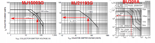
This was off of T Waits thread on resurrecting a Crown DC300A, the15003 are seriously compromised at the supply voltages available from this amp. 21193 would be much better in the higher voltage region of SOAR. The extra current from the 15003 is of no advantage.
The SOA limit on the 21193 is 4A at 60V, the 15003 is 3A at 60V
15003 transistors
jackinnj, i dont know much about how to select eqvlt transistors so I am relying on what I have read. Your response indicating "The SOA limit on the 21193 is 4A at 60V, the 15003 is 3A at 60V " what does it mean in laymen terms? From your experience are the 15003 transistors an acceptable replacement? Please provide quote for 20 pieces delivered to 03051, Hudson, NH. thanks Bob
jackinnj, i dont know much about how to select eqvlt transistors so I am relying on what I have read. Your response indicating "The SOA limit on the 21193 is 4A at 60V, the 15003 is 3A at 60V " what does it mean in laymen terms? From your experience are the 15003 transistors an acceptable replacement? Please provide quote for 20 pieces delivered to 03051, Hudson, NH. thanks Bob
Here's what I mean -- the MJ21193 is a slightly more expensive and faster transistor, ($5.25@ in quantities of 10), ft 4MHz, higher power handling -- the MJ15003 is somewhat inferior with an ft of 2MHz but less expensive. I've also got a few hundred of the discontinued BU208A which was a horizontal deflection transistor -- http://www.st.com/web/en/resource/technical/document/datasheet/CD00000993.pdf nobody needs HV CRT transistors anymore!
Attachments
Good choice.
I have 3 of these amplifiers -- the only thing original in one is the transformer -- it uses the LM4702 as a MOSFET driver and will drive over 200W. I sold the transistors and driver board on EBay -- about 25% of the transistors were shot. The other 2 are going to go under the knife at some point.
I have 3 of these amplifiers -- the only thing original in one is the transformer -- it uses the LM4702 as a MOSFET driver and will drive over 200W. I sold the transistors and driver board on EBay -- about 25% of the transistors were shot. The other 2 are going to go under the knife at some point.
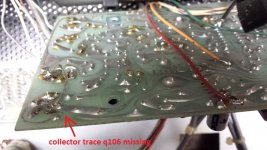
purchased 50 pcs of Sil Pad Classic 400 TO-3 insulator pads. Now have complete set of driver and output transistors for the Channel 1 output board. Last night while inspecting the input board I noticed that both Q106 and Q107 had both been shorted to the face plate, not surprising since the amps face plate was missing all the mounting hardware and had been taped in place. While removing Q106 I noticed that the collector printed circuit board trace had melted and opened. Makes sense since the metallic heat exchanger on Q106 is the collector. The collector shorted to ground.
Q106 tests okay for a double diode test. Will reinstall and repair trace. Without an output from the input board to the output board driver Channel 2 would not work. The previous owner started removing the two output drivers and two of the output transistors. There might not have been any output transistor damage since the driver transistor was not getting an output from the input board. We will never know since the removed transistors did not come with the amp, requiring a complete set of driver and output transistors to be purchased. I have enough to rebuild both channels so they match.
Instead of removing Q107 can I power up amp and measure emitter outputs of Q106 and Q107 using Q206 and Q207 (channel 2 is good) as a reference?
Attachments
Last edited:
I suggest you remove base from all transistors one step back from any blown up ones, and do a leakage test. Double diode test with a 2v meter does not detect stressed transistors. Current leakage test with base shorted to emitter, at some elevated voltage (I use 17 vdc out of a car battery charger) does. I put a 47k resistor in series with the milliammeter so I don't blow up the DVM fuse if I get it backwards. + to C on npn, - to C on pnp. Takes a DVM, a wall transformer or other DC supply, some clip leads, a good transistor for reference on how much leakage is okay.
I found blown up stuff all the way back to the input opamp of my last amp. 50 v rated ceramic caps, resistors, diodes, all blown. 107 parts total. Hope you have better luck. The first amp I fixed, the idle bias current circuits weren't even blown up by the output transistors. Just a matter of luck, I guess, and how many times the owner pushes the breaker button back in and tries again.
I found blown up stuff all the way back to the input opamp of my last amp. 50 v rated ceramic caps, resistors, diodes, all blown. 107 parts total. Hope you have better luck. The first amp I fixed, the idle bias current circuits weren't even blown up by the output transistors. Just a matter of luck, I guess, and how many times the owner pushes the breaker button back in and tries again.
replaced neg and pos predrivers on input board (channel 1). Fixed bad circuit board trace feeding the collector of the positive predriver on the input board. Replaced all output and driver transistors on the channel 1 output board.
How to go about making preliminary measurements while using a variac to power the amp?
I have fed +10VAC to the amp and nothing smoked. I checked the rail voltages on both channel 1 and 2 output boards...measured +9 and -9VDC.
I measured DC between plus and minus speaker terminals. At 10VAC I measured +8VDC on channel 1 (the one with all the rework). I got nervous but when I measured VDC at speaker terminals on channel 2(working channel) I got the same reading?
Is this correct?
Last edited:
djk, Thanks for the advice I will do that. I have a fuse holder currently in series wouldnt reducing that to 1 or 1/2 amp also be of benefit?
I checked the flyback diode on the positive rail on channel 1, dc offset is positive, and it was good. That told me that the voltage might be coming from the input card (current source transistors Q101, Q201 or the zener voltage doubler circuit ). All transistors are new on the channel 1 output card. Using variac bringing line voltage up so the rails meaure 6V. I removed the emitter output (yel/white) of the positive predriver transistor (Q106), since the offset on channel 1 is positive, and the voltage at the speaker terminals reduced from 6 volts or so to less than one volt. I'm going to remove the current source transistors on the voltage doubler circuit next to see if thaey are good. If I remove them I will replace with new transitors. Also want to check the zener. Any advice on how to check that? I still have +6V on channel 2. Which also makes me suspicious of the current source transistors or zener.
Currently with rail voltage at 5.92V, Q106 measures base 6.45V, emitter 6.19V, and 5.92V collector. Doesnt the 6.45V on the base tell me I have the 70V created by the voltage double circuit being used by the current source transistors feeding Q106 , that should measure a bit higher than the 5.9V on the rails.
Last edited:
djk , I am on board now. Instead of using a variac, a 100 watt bulb will be connected in series with one of the 115VAC leads. Once connected apply 115VAC to the amp and turn it on. I would then rely on the light bulbs appearance: if there are no PS shorts the bulb should glow brightly at first then change to a dim glow? If the bulb glows brightly and stays bright remove power, evidence of shorts? Why doesn't the 300 like the variac? Is it because of the zener regulated +70 vdc circuit the current source transistors are feeding off of?
info acquired through various online threads....
The light bulb does act as a fuse in its own right. A 40 watt 120VAC light bulb will draw about 1/3 of an amp. The filament would equal approx. 360 ohms when less current is drawn through it. If more than 1/3 of an amp is drawn through the light bulb...then it will get too hot and melt the filament.
120VAC light bulbs
15W = 1/8 amp and 960 ohms
25W = .21 amp and 576 ohms
60W = 1/2 amp and 240 ohms
70W = .59 amp and 206 ohms
90W = 3/4 amp and 160 ohms
100W = .83 amp and 144 ohms
150W = 1.25 amp and 96 ohms
At turn on the transformer will inrush and the bulb will light brightly. Then will settle down to a smaller overall current and the light bulb might not even light up.
Start small...what will happen is the more current the transformer wants to draw will cause the light bulb resistance to go up and steal more voltage drop and the transformer will see less voltage and current...
Hooked up a 60 watt light bulb in series with the main 120 volt power cord. Hit power rocker switch and the light bulb glowed brightly for 2 seconds and then promptly went to dim you wouldn't even know the light bulb was on. Rail voltages measure 44 volts. DC offset on channel 1 measured 0.9V . Measured base to emitter of one of the driver transistors and it measured 0.6V. DC offset on channel 2 measured 0. Base to emitter on one of the driver transistors measured 0.4 volts.
Can the .9 dc offset on channel 1 be adjusted or is something else going on?
Can the .9 dc offset on channel 1 be adjusted or is something else going on?
Last edited:
.
channel 1 output stage measurements. Positive bias resistor measurement .4V should measure .34V. positive driver voltage base to emitter .61V. Across the emitter resistors of output transistors 0 volts. negative bias resistor measured .42V should be .34V. Negative driver voltage base to a meter measures .6 volts. Across the negative output transistors emitter resistors 0 volts. The procedure in the owners manual to adjust bias resistor voltage is too hand select a resistor that is in a socket on the input Board.
channel 1 output stage measurements. Positive bias resistor measurement .4V should measure .34V. positive driver voltage base to emitter .61V. Across the emitter resistors of output transistors 0 volts. negative bias resistor measured .42V should be .34V. Negative driver voltage base to a meter measures .6 volts. Across the negative output transistors emitter resistors 0 volts. The procedure in the owners manual to adjust bias resistor voltage is too hand select a resistor that is in a socket on the input Board.
- Status
- This old topic is closed. If you want to reopen this topic, contact a moderator using the "Report Post" button.
- Home
- Amplifiers
- Solid State
- Crown DC300A Repair/Restore