Aspiring power amp troubleshooter. Just purchased a DC300A....rough condition. One channel supposedly works the other doesn't. It is outfitted with 3990 transistors (2N5631). The non-operating channel has two missing 3990 output transistors and two missing driver transistors CPN 4579 (2N5804). I want to familiarize myself with basic power amp troubleshooting. I have the DC300 series II schematics and I have the Service Manual. I have perused through Toms legendary Resurrecting a Crown DC300A thread. Great job. I have not powered it up to check the operating channel. I have already removed the rocker switch and the metal bracket. The brackets swaged hardware has failed and the plastic pivot nubs on the rocker are bad. The plastic rocker switch will be drilled out to 7/64" and two small nubs will be lathed out of an acrylic/delrin material and be glued in to the holes in the rocker switch. The brass 3/32" thin wall tubes swaged originally by Leviton will be removed and I was thinking of using a .005" wall 304SS tube that Mcmaster has. The wall should be thin enough to swage the ends.
Can I buy one set of MJ21994 outputs and a pair of drivers?Try to get the nonoperating channel operating then rebuild the operating channel. What is a good replacement for the driver transistors?
Can I buy one set of MJ21994 outputs and a pair of drivers?Try to get the nonoperating channel operating then rebuild the operating channel. What is a good replacement for the driver transistors?
Last edited:
Crown has all the service manual for their old series on their website;
see: Discontinued Amplifier Products
")
see: Discontinued Amplifier Products
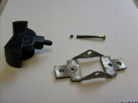
Failed Power Rocker Switch
Mike anything I can share I will. The first thing I need to restore is the Rocker Switch which powers the amp on and off. It has the inherent plastic nub damage to the plastic rocker switch and the failed brass swaged hardware used to hold the switch together. The pivot nubs will be replaced and new brass hardware fab's so the switch can operate correctly, pictures to follow. As soon as the switch is completed I will power the amp and verify if the one channel does operate as the previous owner said.
Mike anything I can share I will. The first thing I need to restore is the Rocker Switch which powers the amp on and off. It has the inherent plastic nub damage to the plastic rocker switch and the failed brass swaged hardware used to hold the switch together. The pivot nubs will be replaced and new brass hardware fab's so the switch can operate correctly, pictures to follow. As soon as the switch is completed I will power the amp and verify if the one channel does operate as the previous owner said.
Attachments
welcome to the forum, these old crown amps are 150w per channel...as your amplifier still got the old white large power caps?
To solve the faulty none working channel and get it running again, remove it from the unit and use the working side to note resistor checks and transistors etc...... sometimes when working on amplifiers with out a schematic handy and there is a channel that does work you have a good start to write down volts such as supply rails and different parts withing that working channel. I recall these old amps give a low thud when powering up to the speaker and if the volume is up your music signal will fade down as its psu drains down at power off.
if your stuck there's more members to pass words of wisdom.
regard.
MJE15032 is kind of a universal TO220 npn driver and MJE10533 is the pnp. If your rails are under 50 v you might get away with TIP41C and 42C which are a lot cheaper. In between there are the MJE15028 and 29. When subbing non-standard transistors, do both push and pull with the same series, or on output transistors make them all the same. No piecemeal subbing on output transistors. I did reuse some OT's as drivers, since my PV-1.3k had TO3 driver transistors.
If your drivers are the old package with the hole in the middle of the plastic, they are probably EBC pattern which is obsolete. I just twist the legs of TO220's around instead of paying high prices for TO126 or whatever they are. If the drivers are TO5 cans, the same applies, but you need to replace the heatsink. I've used sawed up aluminum door frame for heat sinks on drivers before. But when ordering stuff, order the heat sink compound and the mica washers, there is no substitute for those. Wash hands after using heat sink compound.
Sakis wrote a nice "upgrading and repairing old amps" thread, but I'm on the wrong computer to have the bookmark. In general, read high voltage safety on tube thread and follow, 25 v across your heart can kill you and 2 v through a ring can burn your muscle to soot. Use a light bulb box on the AC line when powering up, transistor explosions can blow a die to the ceiling through the steel case. Check everything back from blown output transistors until you stop finding blown up stuff. Note, stressed transistors can pass a double diode test, but leak from collector to emitter with the base grounded at 17 VDC (which I make with a car battery charger and a capacitor. Use a 47k resistor in series with the DVM amps scale you don't want to blow the fuse if the transistor is zorked or you make a mistake).
Sakis & I replace every electrolytic cap over 15 years old before even beginning. If you are not that patient, do the big ones in the power supply right away.
If your power switch blew, maybe the diodes in the DC rail supply are bad. Better check them out of circuit. It is remotely possible your transformer is bad, before I spend a lot of money in parts I usually load the transformer with speaker sim resistors (8 ohm at 250 W or 5 ohm at 450 W) to see how much current it will deliver without heating up. I mount the resistor logs on bits of old steel with turned up tabs in the ends, to keep the resistors from burning the coffee table, and keep the wires straight. When checking a newly repaired amp for sound, I usually put back to back >2000 uf capacitors in series with the trashy checkout speakers, so that a sudden DC event doesn't blow the speakers. I had a bad solder joint on an op amp socket that had been there since 1994 in the last amp I repaired, took a lot of fiddling to find it,it would make nice music for a bit then pop and the output was putting out 160 VDC. Found it with an AC test, music goes inta, not come outa. I use a Simpson 260 with 2 VAC and 20 VAC scale for music tests, rock & roll will make the pointer jump, whereas an oscillation will be a steady AC reading. Use a .47 600 v capacitor in series with the negative probe to keep DC voltage from showing on the AC scale. Scopes are nice, but too full of bad e-caps after 20 years.
Last edited:
Any BJT TO3 can, I tend to use ON semi MJ21193-4G suffix. Everything else is $5.50, they are $4 and they are tough as nails. I think Central and NTE are resellers-rebranders; unless you buy matched PNP-NPN pairs, there is no guarentee that similar matching numbers even came from the same process or factory. ON TO3 parts comes from Mexico, up to now, where the home office QC rep can drop in Saturday night and see for himself which box the rejected parts are going in. When subbing power transistors, I check Ft, Vceo, and SOA current. Vceo has to be higher than twice the rail voltage, and @100 ma specs don't directly compare to @20 ma specs. Think of the power dissipation of 100 ma @ 60V and calculate the power, do want to lose that much heat idling? 2N58xx should be a late process and Ft should not be a problem. I've fixed an early amp that was known for going into oscillation if the original 200 khz Ft transistors were replaced with 4 mhz parts, without some modification.
SOA (safe operating area) has to be bigger than the load puts on it. I read the rail voltage, divide the speaker current at maximum power by number of output pairs, and look at that point on the SOA chart. Replacement has more SOA current than the original, or the number I get from the calculation, we're good. This is ultra conservative, since transistors don't operate at the rail voltage all the time, but like I say, MJ21124 etc is cheaper than inferior parts.
Old transistors don't have SOA specs, and while the maximum current rating is interesting for switching applications at 1.0 V Vce, it is not very interesting for audio applications. Ic max tells you how big the bond wire is , mostly.
I do buy a few extra output transistors and sort, I put 100 ohms to the base and 4.7 ohms to the collector and on my 17 v power supply (battery charger) measure Vce with a DVM. I write the voltage I get on the case with a sharpie and I try to use the weird ones as drivers or something. Out of 22 MJ2119x I put in the PV-1.3k, most were .12-.13 v, two were .11 and became drivers or went in the parts bin.
Hope that helps.
Last edited:
If you haven't read Tom Wait's DC300A rebuild thread yet, it could possibly be helpful in your efforts.
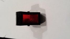
Power rocker switch is complete. The holes in the switch were opened to .110" which will accomodate #4-40 screws. The two holes in the metal bracket were threaded #4-40. The heads on the screws were reduced until they fit in to the counterbore. A 1" long screw works perfectly no shortening required. Switch operates and light works.
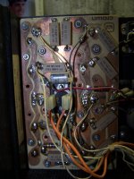
Initial power on confirms that channel 1 IOC light comes on and channel 2 operates as said by the previous owner. The channel 1 power board is missing the two driver transistors and two power transistors. Also missing two of the original transistor insulators. They are made out of a material that looks metallic. Does anybody have two of these available?
WThe four 2N6306 transistors to be used as driver transistors have been recieved.
Will start shopping for power output transistors MJ21194.
Can someone guide me through what checks can be made on the power board once it has been determined that the whole board is populated?
Attachments
Last edited:
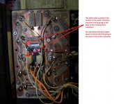
the non operating output board has a white wire coming from the DCA board that terminates at an emitter of an output transistor while the operating channel output board has this white wire going to the base of the driver transistor.
Attachments
- Status
- This old topic is closed. If you want to reopen this topic, contact a moderator using the "Report Post" button.
- Home
- Amplifiers
- Solid State
- Crown DC300A Repair/Restore