Distortion is not remotely random, noise is entirely random.
Induced noise, e.g. hum, ripple, crosstalk is not random.
THD is the sum of noise and distortion.
If amps are paralleled, theoretically thermal noise is reduced.
Output stage distortion is usually related to output current,
and paralleling amplifiers will reduce output stage distortion.
") sreten.
sreten.
Induced noise, e.g. hum, ripple, crosstalk is not random.
THD is the sum of noise and distortion.
If amps are paralleled, theoretically thermal noise is reduced.
Output stage distortion is usually related to output current,
and paralleling amplifiers will reduce output stage distortion.
sreten.Thanx,
so will only parallel amps reduce distortion or also paralleling output devices
Are separate feedback loops necessary ?
I read that some bridge configurations will lead to distortion cancellations of even or odd orders (only). Why ?
Besides parallel DAC chips, I wonder if it is possible to synchronize sine generators as ICL8038 or stuff like that, to reduce distortion.
And op amps...
Bernhard
traderbam said:
If the non-linearity is not symmetrical it doesn't work.
And how do I know if it is sym ?
traderbam said:If you have two identical, non-linear amps which have a symmetrical non-linearity, you can feed signal S into one and signal -S into the other and subtract the outputs to cancel the distortion.
If the non-linearity is not symmetrical it doesn't work.
Erm.... I think you've got this the wrong way round.
Balanced topologies cancel asymmetric distortion but
cannot cancel symmetric distortion.
By using a balanced configuration the asymmetric distortion
is the opposite in the other channel, so they are symmetric in
this sense, which is why they cancel.
Even order distortion is assymetric, odd order distortion symmetric.
sreten.Bernhard said:Hi,
are K2, K3, .... Kn in phase or out of phase (random phase angle) when produced by two identical amps which are fed with same sine signal.
if you feed identical signals to identical amps, the output should be identical, short of any randomness in the process (like noise).
I tend to think distortion (as induced by component or design) isn't random. For example, running an A/C signal through a diode should always yield you a half wave, which in itself is distortion.
traderbam said:If you have two identical, non-linear amps which have a symmetrical non-linearity, you can feed signal S into one and signal -S into the other and subtract the outputs to cancel the distortion. If the non-linearity is not symmetrical it doesn't work.
That is not literally true. For example, you cannot make
intermodulation go away in a like fashion.
Sreten correctly points out that asymmetries are cancelled rather than symmetries, in the case where the distortion can be described by an even ordered power series.
So if the input is x and output is y where y = ax + bx^2 + cx^4 +...
the bridged output will be 2ax.
This suggests to me that the visual symmetry is not the pertinent factor. It is the nature of the distortion. For example, the output of each amp could be y = e^x - 1. This is an asymmetrical function, The bridged output is e^x - e^(-x) which is not linear either, but is symmetrical.
Mathematically the bridge configuration will give you an output function that consists of the odd-order elements of the power series of an individual amp. So it must follow that you should try to make each amp devoid of odd powered elements (except for element 1) and not care about the even ones.
Need to think about this. Does this imply that valve amps sound better when bridged?
That is not literally true. For example, you cannot make
intermodulation go away in a like fashion.
I believe you. I am realising that my earlier comment was far from true. I'm now imagining all sorts of distortions which will not subtract in real circuits. For example when the linearity is frequency dependent. Intermodulation caused in earlier parts of the circuit certainly.
Hi,
Look at how PP circuits work and look at how paralelled operation works....
When you're done with that look at how distortion cancellation works in both or other circuits and I'll bet you'll see the light...
If you're still fascinated, think about how global feedback works...
Think in an abstract way at the speed of electron transfer and you'll spot the bottlenecks...
Also know that any apparent symmetry isn't in really in real life.
Cheers,
I believe you. I am realising that my earlier comment was far from true. I'm now imagining all sorts of distortions which will not subtract in real circuits. For example when the linearity is frequency dependent. Intermodulation caused in earlier parts of the circuit certainly.
Look at how PP circuits work and look at how paralelled operation works....
When you're done with that look at how distortion cancellation works in both or other circuits and I'll bet you'll see the light...
If you're still fascinated, think about how global feedback works...
Think in an abstract way at the speed of electron transfer and you'll spot the bottlenecks...
Also know that any apparent symmetry isn't in really in real life.
Cheers,
fdegrove said:
If you're still fascinated, think about how global feedback works...
Think in an abstract way at the speed of electron transfer and you'll spot the bottlenecks...
Cheers,
I'm a engineer, give me a break, a facetious arguement only for the ignorant.
sreten.Hi,
Ah...It wasn't meant for you and you know it...
Cheers,
I'm a engineer, give me a break, a facetious arguement only for the ignorant.
Ah...It wasn't meant for you and you know it...
Cheers,
Hi,
Regarding distorsion cancellation using parallelled amplifiers or series coupled amplifiers it is important to remember that even if the relationship of phase between the main signal and the harmonics is not random it usually changes a lot depending on input level, temperature, frequencies aso.
Distorsion cancellation is often used to make linear RF power amplifiers with high efficiency and altough you can reach amazing results of cancellation at one power level, at one frequency at one temperature... The reality is that you have to be content with quite small gains due to cancellation methods, close to clipping usually the distorsion increases very rapidly much more rapidly then a normal amplifier without cancellation.
Another thing is that distorsion cancellation usually add new distorsion artefacts as one amplifier with distorsion is added all distorsion products that is not cancelled, (usually high order) will be worse then in an amplifier without cancellation.
Regards Hans
Hi,
Well put, Hans...
I don't know whether you followed this in the tube thread but I once mentioned before I don't want an amp with that kind of distortion spectrum...
Neither does AKSA's CEO Hugh Dean and from the little I follow, neither does Nelson Pass...
At the end of the day the better way to go, regardless of topology, is the one with the distortion spectrum that's easiest on the ear it seems...
Still, one way or the other, we'll need to bring down distortion to within acceptable levels...
The secret is in how much distortion, or at least to me what it contains harmonically, and how to handle it...
Knowing what goes on within the amp AC-wise is often a big pointer too.
Cheers and Merry X-Mass to you,
Another thing is that distorsion cancellation usually add new distorsion artefacts as one amplifier with distorsion is added all distorsion products that is not cancelled, (usually high order) will be worse then in an amplifier without cancellation.
Well put, Hans...
I don't know whether you followed this in the tube thread but I once mentioned before I don't want an amp with that kind of distortion spectrum...
Neither does AKSA's CEO Hugh Dean and from the little I follow, neither does Nelson Pass...
At the end of the day the better way to go, regardless of topology, is the one with the distortion spectrum that's easiest on the ear it seems...
Still, one way or the other, we'll need to bring down distortion to within acceptable levels...
The secret is in how much distortion, or at least to me what it contains harmonically, and how to handle it...
Knowing what goes on within the amp AC-wise is often a big pointer too.
Cheers and Merry X-Mass to you,
I don't know whether you followed this in the tube thread but I once mentioned before I don't want an amp with that kind of distortion spectrum...
Yes, neither would I or indeed if you are working with high efficiency linear RF power amplifiers. After working the last 30 years with very modest results when it comes to improved efficiency the current favorite method is using very small amount of linearisation but feed the amplifier with a digitally controlled predistorded signal that contains unlinearities but in opposite phase, the result is high efficiency and good linearity. However the behaviour at clipping is still very rapid increase of distorsion.
I think no one want to have an amplifier like that for audio, (even if it would measure extremely well at normal levels) cancellation methods sounds like a good idea in theory but usually dont work that well in reality.
Sometimes it is quite easy to see if distorsion cancellation occurs as the 2 IM products that are created by 2 closely located signals will have different amplitiude, I am always suspicious when I see this, (example signals 10 and 11 kHz will give IM products at 9 and 12 kHz, if these are different the cause could be distorsion cancellation)
Regards Hans
tubetvr said:
Another thing is that distorsion cancellation usually add new distorsion artefacts as one amplifier with distorsion is added all distorsion products that is not cancelled, (usually high order) will be worse then in an amplifier without cancellation.
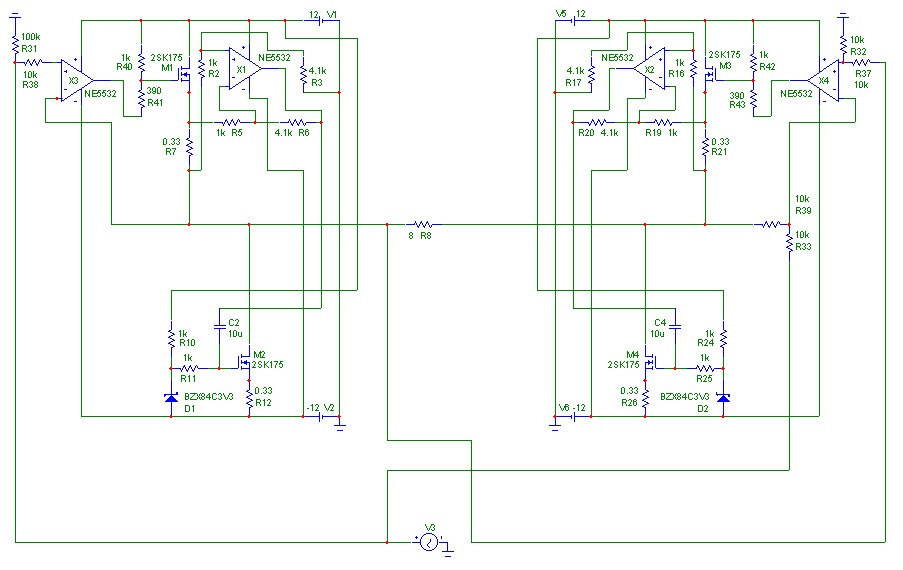
One thing: Will I have to fear this in the below schematic, where an amp on the right side reamplifies the difference between input signal and output signal of the amp on the left side ?
And another thing: It is still a mystery to me, the supersymmetry...
There is feedback from the other side to the positive input.
In my head I always add a nipple
to a halfwave to imagine a higher order signal content.So if a negative halfwave from other side with nipple °( will add to the input signal ), we have a °), and that is what is amplified.
The amplified nipple ° will cause higher order nipples and the halfwave will look like that: Double nipples )°°, triple nipples )°°° and multiple nipples )°°°°°°°°°°°°°
Or do I miss something ?
Symmetrical and asymmetrical - what does it mean ?
That positive and negative halfwaves look the same ?
Like )° and °( ?
Does SE classA produce asymmetrical distortions ? Like )° and ^( ?
And push-pull symmetrical ?
Bernhard
- Status
- This old topic is closed. If you want to reopen this topic, contact a moderator using the "Report Post" button.
- Home
- Amplifiers
- Solid State
- Is distortion random ?