john curl said:I'm sorry, I might be missing something, but I don't see any amazing distortion reduction in the circuit in #37. It looks like a bridged output to me. We have been making amps like this for 1/3 century. They always have low, but real distortion. Also, you have a short on the input. This can be fixed by assigning the opposite input polarities on one side.
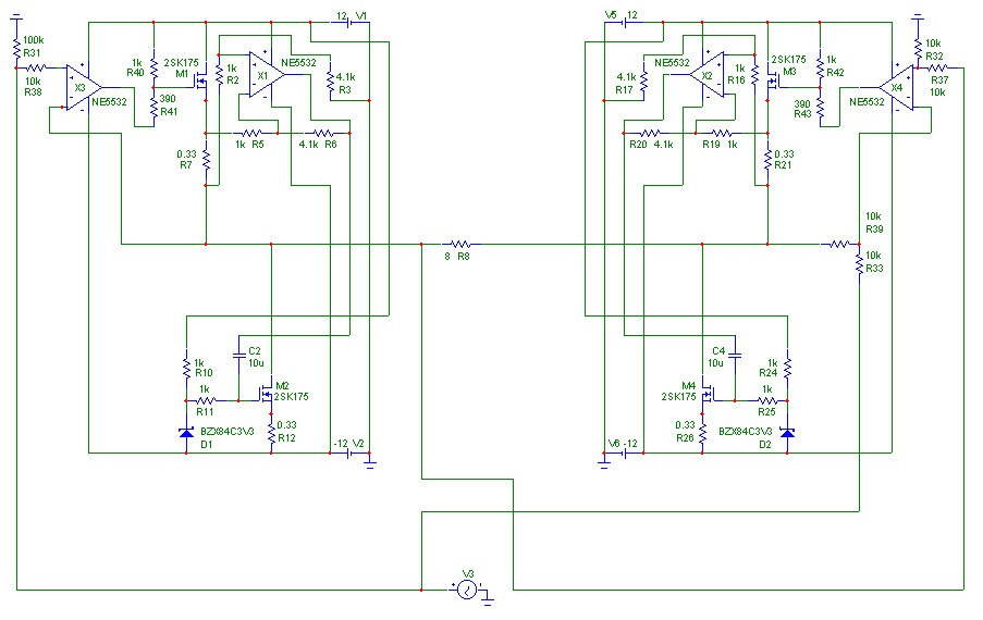
Yes, you are missing something, the op amps are symbols only, but I have written that.
The op amp symbol on the right is marked as "differential amp" and so the input signal is substracted from the left output and the result of that is present on the right output.
If that schematic is not clear, again the real one:
It not only improves distortion values about 35dB, but also is able to compensate clipping of the left output stage.
real hardcore
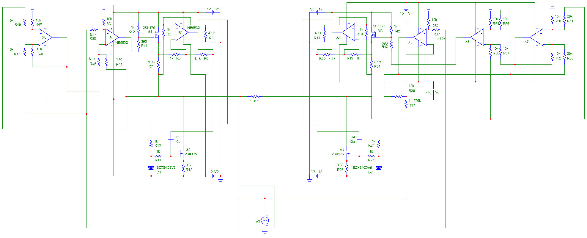
May I proudly present my 2nd version...
The one with distortion -183dB in sim.
Sorry, a big one...
For those who like to understand:
Left side: The input is subtracted from the same side output and the result (distortion) is again subtracted from the input.
Right side: The same, but here the "input" is the result of the subtraction left output minus input.
The subtractions are not pure ones, in some cases I found for best results it has to be something like output = x (+in - -in).
Not so difficult ?
No doubt this works, just the question is how good in the real world.
Offsets voltages are in the range of 100µV throughout the circuit, except 3,5V for driving the gain fets.
Maybe I should try something like INA103 for differential amp
Ok, I do not really intend to built that, its more a kind of study...
The more simple version may be sufficient if it works ok.
Bridged Amplifier
Hi Bernard,
I second Johns post that it is essentially a bridged mode amplifier. See f.a.:
http://eportal.apexmicrotech.com/mainsite/pdf/an03u.pdf
and
http://eportal.apexmicrotech.com/mainsite/pdf/an20u.pdf
Hi Bernard,
I second Johns post that it is essentially a bridged mode amplifier. See f.a.:
http://eportal.apexmicrotech.com/mainsite/pdf/an03u.pdf
and
http://eportal.apexmicrotech.com/mainsite/pdf/an20u.pdf
Bernhard said:
And how do I know if it is sym ?
Odd harmonic distortion is symmetrical.
Jan Didden
I think links reported in Elso message have litte to do
with Bernhard circuit which is an implementation of the well
known feed-forward technique.
see, for instance, at
http://digilander.libero.it/paeng/feedforward_concepts.htm
bye
Federico
with Bernhard circuit which is an implementation of the well
known feed-forward technique.
see, for instance, at
http://digilander.libero.it/paeng/feedforward_concepts.htm
bye
Federico
how much feedback could we have
Let's see what can be done with feedback in principle.
Suppose that the highest unity-gain bandwidth you can practically achieve nowadays is 10MHz. With a simple roll-off of 6dB/oct the open-loop amp could have a gain of 500 at 20kHz. Now, the thing needs some gain in closed loop, let's say 50, so this means the feedback factor at 20kHz would be 10. Therefore to achieve <0.1% closed-loop distortion at 20kHz we'd need <1% distortion in open-loop.
How hard is that to do? Doesn't sound particularly easy.
millwood said:in addition, if there is any time delay / phase shift either in the amp itself or in the feedback network, feeding those signals back will create additional distortion at the output as well, even if the amp itself doesn't create higher order products.
It's all very well trying to cancel out distortion in a simulation, but what about the likely parasitic capacitances in a negative feedback loop, as millwood suggests? Do the simulations take into account physical layouts?
In a typical class-AB topology the open loop gain is likely to be highly non-linear even with extremely linear transistors. A lot of the distortion is likely to occur due to the sudden change in open-loop gain between class-A and class-B operation. One technique to reduce the subjective effects of this may be to operate the amplifier in class-A mode up to a relatively high volume before changing to class-B. Although this might increase the measured distortion, it is likely to be less noticeable at the higher volume and due to the increased speaker distortion.
A method to reduce the actual distortion produced though might be just remembering to keep the feedback loop as small and short as possible. When choosing transistors, perhaps try to choose ones with small parasitic capacitances. Also, I'm sure there are ways to make the openloop gain into a smooth curve rather than a discontinuous step, perhaps working more in that direction could be productive?
CM
- Status
- This old topic is closed. If you want to reopen this topic, contact a moderator using the "Report Post" button.
- Home
- Amplifiers
- Solid State
- Is distortion random ?