Hi All,
I am rather new to the forum, being in "read only" mode for some time.
Some 30 years ago I used to hear the sound coming from Pioneer Exclusive M3 amp and it appeared remarcably good.
After a long break in doing DIY sound staff, I seem to have some spare time and excidentally Exclusive M3 schematics came across. I got really inspired by the concept (class A voltage amp with 2 diff cascades, local NFBs with relatively light overall NFB), used modern transistors, did some modelling in Multisim - it showed exceptional linearity and stability even with overall NFB removed - so I decided to develop an "improved" power amp based on this good old design. I need 7 channels, by the way - really like a high-res multi-channel audio (actually I've got 5 channels with fronts bi-amped, using Audiolab 8000x7 at the moment as a main power amp).
In a nut shell - I have added a dc-servo integrator instead of the capasitor in overall NFB, changed the output stage design to "bryston-type-of" symmetrical cirquit, based on high-current Sanken complimentary pairs and simplified the VA power supply, adding a simple stabilizer in each particular channel (M3 utilized a completely separate stabilised PSU for VA).
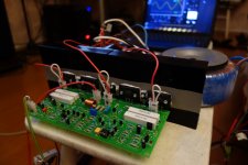
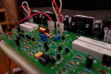
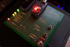
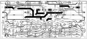
I have assembled a prototype, did some corrections, developed a PCB and finally assembled a second prototype of one channel, which is very close to the final version now (see attached files).
It shows great instrumental performance and excellent sound resolution (I used a pair of Monitor Audio RS8 speakers connected serially to my single prototype channel).
I have developed a protection system based on Arduino controller - finalising prototyping at the moment. It detects DC offset, over-current, over-temperature and AC failure and reacts accordingly, first of all disconnecting speakers and then removing the main power and indicating what happened. It also controlls the soft-start.
The design seems to be very repeatable, no tuning required except output transistors BIAS set (100-120 mA).
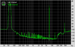
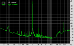
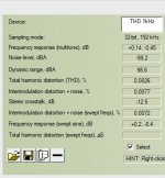
I did some measurements using RMAA, however some people say RMAA is not precise enough, so I have ordered WinAudioMLS from Dr.Jordan Design - waiting for it to come to do deeper measurement.
This prototype will be built as a one-channel amp (for sub or something, though I don'n need subwoofer for music listening, even in multi-channel mode). I have ordered 7 PCBs for the main unit already - looking for appropriate case now - must be pretty big one")
If somebody finds this design interesting - questions, suggestions are welcome.
Perspective of soldering 7 PSBs drives me crazy, but I am full of enthusiasm to complete this project and hear the sound with all the channels in place.
Cheers,
Valery
P.S. How can I link an avatar to my profile?
I am rather new to the forum, being in "read only" mode for some time.
Some 30 years ago I used to hear the sound coming from Pioneer Exclusive M3 amp and it appeared remarcably good.
After a long break in doing DIY sound staff, I seem to have some spare time and excidentally Exclusive M3 schematics came across. I got really inspired by the concept (class A voltage amp with 2 diff cascades, local NFBs with relatively light overall NFB), used modern transistors, did some modelling in Multisim - it showed exceptional linearity and stability even with overall NFB removed - so I decided to develop an "improved" power amp based on this good old design. I need 7 channels, by the way - really like a high-res multi-channel audio (actually I've got 5 channels with fronts bi-amped, using Audiolab 8000x7 at the moment as a main power amp).
In a nut shell - I have added a dc-servo integrator instead of the capasitor in overall NFB, changed the output stage design to "bryston-type-of" symmetrical cirquit, based on high-current Sanken complimentary pairs and simplified the VA power supply, adding a simple stabilizer in each particular channel (M3 utilized a completely separate stabilised PSU for VA).
I have assembled a prototype, did some corrections, developed a PCB and finally assembled a second prototype of one channel, which is very close to the final version now (see attached files).
It shows great instrumental performance and excellent sound resolution (I used a pair of Monitor Audio RS8 speakers connected serially to my single prototype channel).
I have developed a protection system based on Arduino controller - finalising prototyping at the moment. It detects DC offset, over-current, over-temperature and AC failure and reacts accordingly, first of all disconnecting speakers and then removing the main power and indicating what happened. It also controlls the soft-start.
The design seems to be very repeatable, no tuning required except output transistors BIAS set (100-120 mA).
I did some measurements using RMAA, however some people say RMAA is not precise enough, so I have ordered WinAudioMLS from Dr.Jordan Design - waiting for it to come to do deeper measurement.
This prototype will be built as a one-channel amp (for sub or something, though I don'n need subwoofer for music listening, even in multi-channel mode). I have ordered 7 PCBs for the main unit already - looking for appropriate case now - must be pretty big one
If somebody finds this design interesting - questions, suggestions are welcome.
Perspective of soldering 7 PSBs drives me crazy
, but I am full of enthusiasm to complete this project and hear the sound with all the channels in place.Cheers,
Valery
P.S. How can I link an avatar to my profile?
Attachments
-
 PA-Pio_00001.jpg297 KB · Views: 733
 -
 PA-Pio_00002.jpg276.7 KB · Views: 691
 -
 PA-Pio_00003.jpg290.1 KB · Views: 652
 -
 PA-Pio_00004.jpg290.3 KB · Views: 610
 -
 PA-Pio_00007.jpg399.1 KB · Views: 606
 -
 PowerAmp-pio-sch-v01.jpg797.4 KB · Views: 561
 -
 PowerAmp-pio-pcb-v01.jpg656.1 KB · Views: 529
 -
 imd.png4.8 KB · Views: 187
 -
 thd.png4.6 KB · Views: 244
 -
 PowerAmp-pio-TEST.JPG31.8 KB · Views: 348
Member
Joined 2009
Paid Member
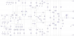
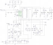
Original schematic
Here is the original: Pioneer M3 Exclusive
I use a bit lower current at VAS output (current mirror) - around 6.5 mA, however still staying in class A there.
I also use transistors as diodes instead of diodes at the current sources for diff cascades for better temperature stability.
BTW, output stage idle current trimmer (VR1) is used the danderous way in the original design - if it loses the contact, the idle current goes high...
In my design, if it loses contact (R32) - idle current comes to zero.
I use 50 Ohms trimmer in the prototype, changing it to normal resistor after building the final assembly (that's why I have 3 resistors R32-R34 there).
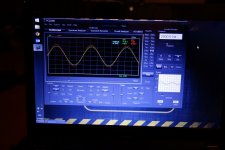
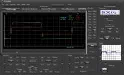
Correction did not require any changes except C12 (at my schematic) - I have increased it from 10pF to 15pF after practical testing the prototype (almost no overshoot when driving a high frequency square wave). See the attached picture - output is green (20 kHz, 20 Ohms / 15W resistor at the output - have not got any smaller one here at the moment).
What I also like a lot - this VAS design provides a very soft and very symmetric clipping - exactly the way I'd like it to be.
original scheme?
Here is the original: Pioneer M3 Exclusive
I use a bit lower current at VAS output (current mirror) - around 6.5 mA, however still staying in class A there.
I also use transistors as diodes instead of diodes at the current sources for diff cascades for better temperature stability.
BTW, output stage idle current trimmer (VR1) is used the danderous way in the original design - if it loses the contact, the idle current goes high...
In my design, if it loses contact (R32) - idle current comes to zero.
I use 50 Ohms trimmer in the prototype, changing it to normal resistor after building the final assembly (that's why I have 3 resistors R32-R34 there).
Correction did not require any changes except C12 (at my schematic) - I have increased it from 10pF to 15pF after practical testing the prototype (almost no overshoot when driving a high frequency square wave). See the attached picture - output is green (20 kHz, 20 Ohms / 15W resistor at the output - have not got any smaller one here at the moment).
What I also like a lot - this VAS design provides a very soft and very symmetric clipping - exactly the way I'd like it to be.
Attachments

Arduino - amp management
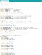
Arduino is a tiny real-time microcontroller. I have written a small program (C-based programming environment, see attached fragment) - it receives the alarms from the sensors (power button or 12v trigger on/off signal, DC offset, current overload, AC failure, overheat) and controls the soft-start relays, speaker connection and LED indicator (showing the error code after the system locks-up in standby after one of the "problem" sensors alarm).
Controllers utilises hardware-assisted interrupts for the most critical alarms (DC offset and current overload), so its reaction is very fast - first of all disconnecting the speaker and then switching om the main power.
Very simple, convenient, flexible approach, from my perspective.
You can add sensors, improve algorythm, change delays, extend indication the way you like, though I like minimalism here - everything is shown with one red LED. One flash every 2 seconds - AC failure, 2 flashes - overheat, 3 flashes - overload, fast constant flashing - DC offset at the output. Something like that...
I will publish more description as soon as the design is fully finalised. Yesterday just finished current overload sensor desigh. Need to experiment with DC offset sensor now
What that "Arduino Module" (it seems) is for? Volume control?
Arduino is a tiny real-time microcontroller. I have written a small program (C-based programming environment, see attached fragment) - it receives the alarms from the sensors (power button or 12v trigger on/off signal, DC offset, current overload, AC failure, overheat) and controls the soft-start relays, speaker connection and LED indicator (showing the error code after the system locks-up in standby after one of the "problem" sensors alarm).
Controllers utilises hardware-assisted interrupts for the most critical alarms (DC offset and current overload), so its reaction is very fast - first of all disconnecting the speaker and then switching om the main power.
Very simple, convenient, flexible approach, from my perspective.
You can add sensors, improve algorythm, change delays, extend indication the way you like, though I like minimalism here - everything is shown with one red LED. One flash every 2 seconds - AC failure, 2 flashes - overheat, 3 flashes - overload, fast constant flashing - DC offset at the output. Something like that...
I will publish more description as soon as the design is fully finalised. Yesterday just finished current overload sensor desigh. Need to experiment with DC offset sensor now
Attachments
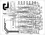
Management Board
Just finished management board design, including PCB (for one channel so far).
Providing standby power, taking care of soft-start from a switch or a trigger, protection from DC offset, current overload, overheat, AC failure, and performing a single-LED status indication.
Partially prototyped, but need complex testing after soldering and putting everything in place. Will let you know how it goes
Cheers,
Valery
Attachments
I've used an ATMega16 for the same purpose: power on/off, softstart control (600 VA toroid), DC output protection, rail voltages monitoring (so I can control also if the softstart relay is working or not), heatsink temperature monitoring.
I use 4 red LEDs to "display" a failure in one of the protections, and 4 green if everything is ok.
Regards,
Roberto
I use 4 red LEDs to "display" a failure in one of the protections, and 4 green if everything is ok.
Regards,
Roberto
I've used an ATMega16 for the same purpose: power on/off, softstart control (600 VA toroid), DC output protection, rail voltages monitoring (so I can control also if the softstart relay is working or not), heatsink temperature monitoring.
I use 4 red LEDs to "display" a failure in one of the protections, and 4 green if everything is ok.
Regards,
Roberto
Cool! Micro-controllers are great for this purpose - compact, easy to maintain the right timings, flexible algorythm... want to improve something? Just connect via USB and upload an updated program

Slowly but surely
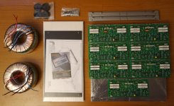
7-channel is progressing.
Yesterday received a top quality enclosure from Italy. Had no time to unpack - first thing to do tomorrow.
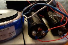
Transformers are ready. PCBs are roughly 50% soldered. 7 pieces - takes time
Started seeing some light in the end of the tunnel... hope it's not a train )))
Cheers,
Valery
7-channel is progressing.
Yesterday received a top quality enclosure from Italy. Had no time to unpack - first thing to do tomorrow.
Transformers are ready. PCBs are roughly 50% soldered. 7 pieces - takes time
Started seeing some light in the end of the tunnel... hope it's not a train )))
Cheers,
Valery
Attachments
- Status
- This old topic is closed. If you want to reopen this topic, contact a moderator using the "Report Post" button.
- Home
- Amplifiers
- Solid State
- PowerAmp Pio 7-channel Project