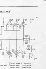
The one I saw had two transistors as the driver stage, and 5 pairs of paralleled mosfets at the output. It is very similar though.It was definately a MF a370.
A few transistors in the opamps power supply line, too. It is possible it was revised slightly, as there were 3 versions of the A370.
A few transistors in the opamps power supply line, too. It is possible it was revised slightly, as there were 3 versions of the A370.
A schematic was posted to this site some time ago, use a Google search on MF A370 to pick it up.
Does anyone know whether the J83 and K226 devices used in the A370 are still available?
Has anyone any more details on these devices which I assume are Mosfets?
Regards
Marcus (First Post!!)
Does anyone know whether the J83 and K226 devices used in the A370 are still available?
Has anyone any more details on these devices which I assume are Mosfets?
Regards
Marcus (First Post!!)
"don't fully understand the VAS stage, and the transistors in the opamp stage, but yes, mosfets."
The BJT in the opamp stage are just a level shift (cascode). The outputs are the VAS.
Same basic idea as the Transnova from Hafler/Acoustat.
http://www.diyvideo.com/forums/attachment.php?postid=182299
The BJT in the opamp stage are just a level shift (cascode). The outputs are the VAS.
Same basic idea as the Transnova from Hafler/Acoustat.
http://www.diyvideo.com/forums/attachment.php?postid=182299
thanks djk, re the 2nd stage, it looks like some kind of beta enhanced VAS stage, as thought the first transistor is feeding the 2nd in darlington arrangement?
and the output mosfets, I find it easier to think in terms of bipolars, the output being from the collector, so there is voltage amplfication taking place.
question, I thought the ouptut stage should have a really low output resistance, it will be quite high from the drain(collector), giving voltage amplification will it not, MF use this in a few outputs.??
Anyone know about the A470? I believe it is the same but has 11 pairs of paralled fets, and chokes in the psu? anyone any info?
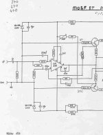
The showed schematics is a first edition, this layout was used unchange for P140/P170 and for the A200/B200 int.amp.
For the P270/A370 improvements was made very rapidly after the release of this first version, by added reg. supply for the LM318, some changes of resistor values, after it succeded very well used in the A370
a buffer-stage was implanted betwin the front-end and the MOSFETs also in the P270, fact is that the P270 came in four different versions.
The last series of the P270 used 2SJ162/2SK1058
2SJ162/2SK1058 is not exactly the same as the 2SJ82/2SK226 (p170/P270) 2SJ83//2SK227 (A370/A470)
few changes/adjustments has be made to insure stability.
(ferrit leads for the gates, misc values of the resistors)
The a470 is roughly just a A370 with regulated power-supply and change of the cab/housing.
Already in 1990 is was imposible!!!
to find a stock of 2SJ82/2SK226 or 2SJ83//2SK227
Hitachi was asked and they had none of these MOSFETs
they was soldout for use in PA amps
If MOSFET-Amps is of prference
The showed schematics is best used with 2 pairs of 2SJ50/2SK135 and if small changes is made of the schematics, it actully sounds incredeble! even messured with todays standards
MF could not have the small versions beat the big ones you see (cost vs. performence)
Here we got the link for the A370, but its unfortunate only the MK II version
http://peufeu.free.fr/audio/schemas/musical_fidelity_a370.gif
http://peufeu.free.fr/audio/schemas/musical_fidelity_a370.gif
try this for size, dunno if its what you are after, Jan
http://peufeu.free.fr/audio/schemas/Audio_Research_D400a.JPG
That's the schematic I was after for the a370.
I don't quite understand you re. the info. are you saying the first posted links at the beginning of the thread are the mk1, and it was changed later to the one shown on page 2 of this thread?
And the 2nd stage is simply a buffer?
try this for more mf schematics, sadly mf are very paranoid about letting the world see their fairly normal designs, I don't know what they have to hide.
http://mujweb.cz/veda/mikes/hifi/schémata.htm
and here...along the left hand side of the page....good for these russian guys!!
http://www.zeuslab.newmail.ru/
about time some good stuff was brought into the public domain.!!
- Status
- This old topic is closed. If you want to reopen this topic, contact a moderator using the "Report Post" button.
- Home
- Amplifiers
- Solid State
- schematic a370