Hello everybody!
I the past i've heard a preamplifier with JFets.
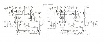
The original schematic was designed for phono preamplifier with passive RIAA equalization between the two main gain pcb.
The passive RIAA equalization is provided by R24 - R25 & C18 - C19 network.
In the preamplifier that i've heard the line input was bypassed to the 2nd pcb after the RIAA network.
I'm interested of constructing a line preamplifier with this schematic.
The original JFets was the E231 from Siliconix ( Q1-Q2), the Q3-Q4 are the BC182, Q5-Q6 are the BC212, Q7-Q9-Q10-Q12 are MPSA56 and Q8-Q11-Q13 are the MPSA06.
I couldn't find the E231 but i've got the U231 dual Jfet and all the other transistors.
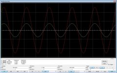
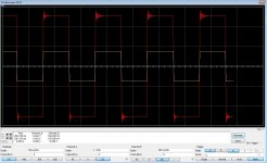
I made the schematic on Multisim, everything ok on the sine but there is a distortion on the square pulse of 1Khz..
Could someone help about the components needed to complete the schematic as line preamp? Input-output filter maybe ? Some mistake as it is now ?
All the components values are on the Multisim file..
Thanks a lot!!
I the past i've heard a preamplifier with JFets.
The original schematic was designed for phono preamplifier with passive RIAA equalization between the two main gain pcb.
The passive RIAA equalization is provided by R24 - R25 & C18 - C19 network.
In the preamplifier that i've heard the line input was bypassed to the 2nd pcb after the RIAA network.
I'm interested of constructing a line preamplifier with this schematic.
The original JFets was the E231 from Siliconix ( Q1-Q2), the Q3-Q4 are the BC182, Q5-Q6 are the BC212, Q7-Q9-Q10-Q12 are MPSA56 and Q8-Q11-Q13 are the MPSA06.
I couldn't find the E231 but i've got the U231 dual Jfet and all the other transistors.
I made the schematic on Multisim, everything ok on the sine but there is a distortion on the square pulse of 1Khz..
Could someone help about the components needed to complete the schematic as line preamp? Input-output filter maybe ? Some mistake as it is now ?
All the components values are on the Multisim file..
Thanks a lot!!
Attachments
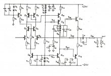
Yes, you have to place an input filter (e.g. 1k/33k//100pF)...but gain in your amp is way to high for line preamp (32x) you should aim for something like 4-6x and compesate for reduced gain, otherwise amp will not be stable...put a small capacitor over R18 (like 10-33pF) and play with the C11 value.
Hello,
Your information are correct indeed!
From the Siliconix Data book the E231 cross the J231 single n-JFet.
I couldn't find either E231 or J231.
Linear Systems have a Cross Reference catalog that had both of them crossed to LS842 Dual Jfet. (page 9-10)
U231 dual Jfet also cross LS842 and it was the only one from Siliconix that i could found after a lot of effort.. (I took it for the matched pair)
E231/J231 could be replaced from BF244/BF245 and 2N5458 i think..
Attachments
You are correct, I use the BF245C FET in my guitar preamps - but in a much simpler design than yours.With a minimum drain current of 12 mA, you can replace Q3-7 with resistors and keep the current sources Q8 and Q11 - but scale the current requirements accordingly to drive the driver transistor Q10 - which will drive the push pull amplifier pair Q12 and Q13, using simple output transistors like the BD139, BD140 to drive headphones and the output amplifier.
For a starter you could read your pm")
Hi,
Arrange input filter as in "blind" schematic in your first post: R1=1k, R2=33k, C4=100pF (for now, you don't need following components FB=ferrite bead, C1=RF filter=small cap in few tens of pF range, could be in series with small value resistor connected directly, as close as possible over input connector signal ground to chassis ground)
As for output, you can leave out both output capacitors (these are for blocking DC offset on preamp output, but then you have to place DC offset control inside preamp, like if you replace R9/R10 with one 100-200R trimmer, wipper connected to R8 and Q8 collector. At output place R30 in 33-100R range and R31 in 10k-100k range.
That being sad, don't afraid to ask question like these in your thread, you will get greater response and I could be wrong in some details or something could be design better.
So you have my permission to copy/paste this text in your thread if you feel like it.
Thanks a lot!
- Status
- This old topic is closed. If you want to reopen this topic, contact a moderator using the "Report Post" button.
- Home
- Amplifiers
- Solid State
- JFet Preamplifier - Help needed..