Hi,
been searching for an answer but didn't succeed (maybe due to a lack of language knowledge ).
).
In most Spice sims I find only a resistor (4 or 8 ohms) as the load for amp performance simulations, sometimes there's a cap in parallel. Has anyone some sort of a "lib" of usual real-world complex loads? Let's say some simple speaker, a usual 3-way one and a rather challenging one?
TIA, Holgi
been searching for an answer but didn't succeed (maybe due to a lack of language knowledge
).In most Spice sims I find only a resistor (4 or 8 ohms) as the load for amp performance simulations, sometimes there's a cap in parallel. Has anyone some sort of a "lib" of usual real-world complex loads? Let's say some simple speaker, a usual 3-way one and a rather challenging one?
TIA, Holgi
here , let me Google (forum search) that for you...
A community dedicated to helping everyone learn the art of audio. Projects by fanatics, for fanatics! - Search Results for spice loudspeaker model
A community dedicated to helping everyone learn the art of audio. Projects by fanatics, for fanatics! - Search Results for spice loudspeaker model
I use a big 4 ohm speaker for my testing new amps. It is 650WRMS so can take a bit of punishment.
However DC will kill it if there is a fault.
So I power up the amp and listen for hum in the speaker, if there is hum then the power supply is being overloaded and I switch off immediately.
However DC will kill it if there is a fault.
So I power up the amp and listen for hum in the speaker, if there is hum then the power supply is being overloaded and I switch off immediately.
An externally hosted image should be here but it was not working when we last tested it.
Buy Bob's book -- it's full of good stuff.
Hi,
been searching for an answer but didn't succeed (maybe due to a lack of language knowledge
In most Spice sims I find only a resistor (4 or 8 ohms) as the load for amp performance simulations, sometimes there's a cap in parallel. Has anyone some sort of a "lib" of usual real-world complex loads? Let's say some simple speaker, a usual 3-way one and a rather challenging one?
TIA, Holgi
Your countryman is well made.
I always use a simulation of a real load to my amp.
Sorry, I could not upload. Look at
http://micka.de/org/en/download/spice-tsp_en.pdf
Attachments
Thank ya all, that's loads of stuff to read
@sreten: Just reducing the resistive load to some reasonable smaller value doesn't win the game. A pure resistor is in no way reactive as a real speaker(-box) is.
@nigel: For measurements when the amp is built-up this is fine. But for simulation you leave me alone... hmm... Do I have to connect the speaker to D+ and D- of a USB port and install a Sim-driver? (just kidding)
@rajko: Looks pretty interesting, mostly since the results are comparable to what I achieved so far.
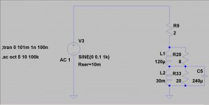
So here is a comparison of 1khz 50/50 pulse driven into a pure 8R load (no schematic) and into a 3-way speaker for which I modeled the speaker chassis 1-by-1 along with the xover - but w/o box, showing output voltage and current.


Again, thank you! I now will start to model the box and see how it influences the response.
BR,
Holgi
@sreten: Just reducing the resistive load to some reasonable smaller value doesn't win the game. A pure resistor is in no way reactive as a real speaker(-box) is.
@nigel: For measurements when the amp is built-up this is fine. But for simulation you leave me alone... hmm... Do I have to connect the speaker to D+ and D- of a USB port and install a Sim-driver? (just kidding
)@rajko: Looks pretty interesting, mostly since the results are comparable to what I achieved so far.
So here is a comparison of 1khz 50/50 pulse driven into a pure 8R load (no schematic
) and into a 3-way speaker for which I modeled the speaker chassis 1-by-1 along with the xover - but w/o box, showing output voltage and current.
Again, thank you! I now will start to model the box and see how it influences the response.
BR,
Holgi
And always remember that real world loads, as speakers are dynamic and never the same. A transmissionline or bassreflex speaker has huge resonances which will show up in great detail in the feedback path in your amplifier.
You would get the best understanding if you laplaced your amplifier and have a look at the poles and zeros.
You would get the best understanding if you laplaced your amplifier and have a look at the poles and zeros.
audio frequency amp output/loudspeaker load interaction is characterized by damping factor vs frequency, which is the amp output (complex) Z vs frequency divided by the load Z at the same frequency
we typically have huge damping factor and therefore little amp Vout reaction to load Z variation at audio frequencies with the standard low output Z negative feedback audio power amp circuits
what does vary is the current supplied to the load - and the output devices, their drivers, bias and the power supply, heatsinking all have to be designed for the expected real world load current over the range of phase angle
but if you have competently designed, sized the outputs, ect. - then the usual result is there is almost no influence on stability for audio frequency complex loads
and the distortion is pretty much the same or less for complex load vs the same I delivered into a pure R
that "real workd loads are difficult for amplifiers" seems a popluar meme though:
...do we really have to reprise all of the ca 1980 JAES findings re Otala and fanboys "suspicions" which have been proved conceptually flawed or irrelevantly low, easy to overcome without his tweak recommendations?
The output impedance “interface distortion” comments should make any competent engineer blush – Cordell, Self “textbook” audio amp theory and measurements, JAES articles by Cherry, et al
look on Klippel's site if you are serious about bounding dynamic speaker electrical terminal nonlinearities
but you also need to tighten up your reasoning about said speaker impedance distortion and which type amps reject it better
almost everything about an amplifier's output at audio frequencies into complex speaker loads can be seen with a "tug-of-war" test - a (bigger) amp on the other end of a power R load - driven with phase shifted test signal
you can also drive the other end of the power R with different frequencies, multi-tones, emulate nonlinear loads
Last edited:
done been discussed:
to my ears continually referring to “back emf” in describing loudspeaker/amplifier interaction is extremely dissonant, like using “scattering coefficient” for resistance or “recombination rate” for transistor current gain – it is a physically correct, useful concept at a detailed level in the modeling hierarchy but using it where the higher level model works is a kind of intellectual “thought impediment” akin to stuttering in speech – it derails more discussions of dynamic loudspeaker behavior than it informs
the useful electrical terminal model of a dynamic loudspeaker is that of a complex impedance composed of the voice coil electrical parameters coupled to a electro-mechanical transformer that converts the force and velocity at the voice coil to electrical terminal I and V – the mechanical mass, spring constant and damping of the cone/suspension/box look like additional C, L, and R at the dynamic driver’s electrical terminals
the linear model of the loudspeaker load as a complex impedance network gives pretty useful estimates of I, V and phase with whatever signal you care to convolve with it
dynamic loudspeaker drivers are noticeably nonlinear, particularly at low frequencies, these nonlinearities can be accommodated in the electrical terminal model of the driver, see:
http://www.klippel.de/background/introduction.asp
you can find hard numerical data in Klippel’s work that permits putting strong limits on how much loudspeaker nonliearities can influence dynamic driver electrical terminal behavior
as ingrast has pointed out laundry lists of possible physical effects are not useful to the engineer until you can put numbers on them to rank their relative influence, Klippel’s models let you bound the possible effects of driver nonlineariy
one physical effect that can readily be dismissed by consideration of the numbers is “microphone” effect:
dynamic loudspeakers are “bi-directional” transducers so that the law of reciprocity applies; a loudspeaker is as efficient in converting incident sound pressure on its cone to electrical terminal I,V as it is in converting the electrical input to sound – since direct radiator dynamic drivers struggle to reach even 1% efficiency any “round trip” electrical – sound – electrical effects are < 0.01% of the power into the speaker’s electrical terminals, since we are dealing with driver resonace peaks, voice coil heating dRseries and crossover impedance dips of > +100%/-50% the microphone behavior of the loudspeaker is merely a curiosity
- Status
- This old topic is closed. If you want to reopen this topic, contact a moderator using the "Report Post" button.
- Home
- Amplifiers
- Solid State
- Simulating real-world loads?