Since I normally drag things on for much too long, I'll describe my situation with bullets.
Now that I am in possession of these boards, I'm parts-buying, and looked back at the schematic again and noticed I forgot to include R4 and R5; from what I've read, they provide some sort of initial bias for the preamp, which is required and will require some tinkering.

Since I'm not using phantom power, I won't need the phantom power circuit, or C1 and C2. I omitted the output control loop too, since that would just take up more board space (PCBs are expensive!) .
How much gain am I most likely going to be needing to output 500mV p2p max for the ADC from a
5. Should I add an output capacitor to reduce/eliminate DC output bias, and does it require a resistor as well (for a HP filter?)?
Sorry for the flood of questions.
Thanks!
- Want high-grade PC audio input for microphone, guitar, and guitar amp
- Cheapest mixer is $50 and is a crappy behringer
- For some strange reason decide not to go with USB mics
- Buy an XM8500 cardoid mic
- Have nothing to pre-amp it with
- Datasheet notes 500mV input voltage
- Nothing to amplify cardoid mic
- INA217 looks pretty nice
- Design a board for power supply (+/-15v)
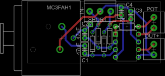
- Design a simple board for the INA217 (See attachment)
- order both of these
Now that I am in possession of these boards, I'm parts-buying, and looked back at the schematic again and noticed I forgot to include R4 and R5; from what I've read, they provide some sort of initial bias for the preamp, which is required and will require some tinkering.
Since I'm not using phantom power, I won't need the phantom power circuit, or C1 and C2. I omitted the output control loop too, since that would just take up more board space (PCBs are expensive!) .
How much gain am I most likely going to be needing to output 500mV p2p max for the ADC from a
- Cardoid mic
- Electric/acoustic guitar
- Guitar amp
5. Should I add an output capacitor to reduce/eliminate DC output bias, and does it require a resistor as well (for a HP filter?)?
Sorry for the flood of questions.
Thanks!
Attachments
With long leads, it would be a good idea to put some RFI protection on the inputs -- say 100pF from each input + and - to ground, and 220pF between + and - IN. Since you suggest that it may be subject to "hot plugging" you might also consider putting 10R or 47R between each of C1, C2 and their respective clamping diodes to limit current.
2k2 + 47uF gives you an f3 of 1.5Hz.
You can substitute SSM1019 for INA217. The inputs of the SSM2019 are protected with diodes across the base-emitter junction of the input transistors AND clamp diodes to prevent the input from going beyond the rail voltage (or so says the datasheet)!
You can substitute SSM1019 for INA217. The inputs of the SSM2019 are protected with diodes across the base-emitter junction of the input transistors AND clamp diodes to prevent the input from going beyond the rail voltage (or so says the datasheet)!
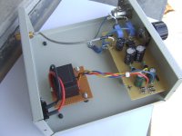
I built INA217 based mic pre as in DS schematic without RFI caps and on the perf board (I do not have possibility to etch my own pcbs) and it worked just fine. Used ordinary 78L15 and 79L15 regulators with RC output filter.
The best of all opamps for mic pre is THAT 1510/1512. (Better than INA or SSM)
The best of all opamps for mic pre is THAT 1510/1512. (Better than INA or SSM)
Attachments
Last edited:
I built INA217 based mic pre as in DS schematic without RFI caps and on the perf board (I do not have possibility to etch my own pcbs) and it worked just fine. Used ordinary 78L15 and 79L15 regulators with RC output filter.
The best of all opamps for mic pre is THAT 1510/1512. (Better than INA or SSM)
looking at your board, it seems you have a vertical output cap right there - is that necessary and should I put one there too?
Is there any particular reason I would want a low pass input filter, and if there is, how would I find non-electrolytic capacitors with that value?2k2 + 47uF gives you an f3 of 1.5Hz.
You can substitute SSM1019 for INA217. The inputs of the SSM2019 are protected with diodes across the base-emitter junction of the input transistors AND clamp diodes to prevent the input from going beyond the rail voltage (or so says the datasheet)!
If you look at the attached board, I already have input protection diodes in their respective places. I'll check out the THAT but if it requires a whole new board design I'll stick with the ina217.
cheers.
Last edited:
IThe best of all opamps for mic pre is THAT 1510/1512. (Better than INA or SSM)
Agreed, but the ThatCorp opamps are only available through Mouser in the US.
WIMA has some low voltage (16VDC and 50VDC) polyester caps with high capacity (Mouser carries). WIMA
There really isn't too much wrong with using a quality electrolytic like the Elna Silk (available from DK) in this application.
looking at your board, it seems you have a vertical output cap right there - is that necessary and should I put one there too?
If you do not use opamp dc offset servo (like in INA217 DS schematic) output cap is absolutely necessary. You can omit it only if you know that input of mixer has input cap. But if you want to have mic pre that you can use with unknown mixer, premap, etc., output cap should remain in place.
If you do not use opamp dc offset servo (like in INA217 DS schematic) output cap is absolutely necessary. You can omit it only if you know that input of mixer has input cap. But if you want to have mic pre that you can use with unknown mixer, premap, etc., output cap should remain in place.
I read somewhere that it only needs to be ~16v or so because the output offset shouldn't get higher than that, but what capacitance?
- Status
- This old topic is closed. If you want to reopen this topic, contact a moderator using the "Report Post" button.
- Home
- Amplifiers
- Solid State
- INA217 Mic Preamp