Member
Joined 2009
Paid Member
If 'simpler' and 'lower power' means a layout without the MOSFETs then I would be more interested in waiting for that")
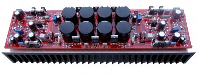
What you want is shown in the photo - it's not my amplifier though. This is one from the stable of Hugh Dean. It has an on-board power supply with lots of filter caps. It is stereo and is a simple amplifier based on a singleton input and MOSFET outputs.
Look at the size of the pcb - this is much larger than I can do with my free copy of Eagle. He doesn't include speaker protection though - doesn't feel it is required, plus he designs it to have minimal turn-on noises. That heatsink you see is 75mm x 300mm, that's a big pcb.
I've shown that I can fit a mono channel and filter caps onto a board but it's tight and I'd have to redo the layout for good ground return from the filter caps. But to to fit a stereo amp and simple psu on a board only 10cm x 8cm I think you have proposed quite a challenge. The dc protection circuitry does take up space - it's nearly as complicated as the amplifier itself, everything costs you space. However, a lower power version doesn't need the MOSFETs. I'll give it some further thought.
Would you consider using Lateral FETs for the output devices instead of bipolar devices ? - they are quite robust, more linear than regular vertical mosfets, not fussy about their bias. We might be able to eliminate the Vbe multiplier altogether.
Attachments
Last edited:
I'm aware of Hugh's amplifiers and one day hope to hear one in person. All reports from those I know that own one are outstanding. He's an Aussie too (albeit from Melbourne, not the Sunshine State
I've jumped on Meanman's Latest Fetzilla group buy that Hugh had a hand in designing.
There is no way to layout a stereo board with respectable filter bank all within the 100x80cm limitations. No way - that's not what I was suggesting. But perhaps a stripped down stereo board (no power supply or fets) or perhaps a mono board sans FETs but with the filter caps? I like the idea of an offboard 35A bridge rectifier bolted to the chassis.
Personally I think the input cap and DC protection circuit should be there regardless of any other options or configurations.
I like the latfet idea and was actually going to suggest that a while ago. If you can eliminate the Vbe then all the better. I guess then it will be a completely different design to the P3A.
I'd like to try both your designs
Hi Rachu32,
You know I once lived in Brisbane, and even during 1972 in Townsville!
If you live not too far from Redland Bay I can link you with a very nice guy who has a NAKSA 80........
Amps under 100W generally don't need loudspeaker protection as long as rails are less than 45V. It's an economy issue, and what the market expects to pay. Larger amps are usefully given DC protection, as this has no deleterious on the sound quality, if you ignore the relay issue, though that is now being supplanted by mosfet relays.
You don't need a Vbe multiplier, just as you say, if you use latfets.
Advantage of integrating power supply with amp is reduction of wiring, and removal of the idiot factor, which destroys a lot of amps during installation.
Cheers,
Hugh
Member
Joined 2009
Paid Member
For my home theatre application I may be able to avoid using a relay on each channel of the amplifier by using a single protection per power rail located at the main power supply. This will shut the whole amplifier down if any of the channels gets naughty at the output. This keeps it simple. But this approach works best with multiple channels being fed from a centralized power supply filter bank.
For stereo applications it's a bit of a wash, since cutting off two power rails isn't so much different from cutting off two speaker outputs.
For stereo applications it's a bit of a wash, since cutting off two power rails isn't so much different from cutting off two speaker outputs.
Last edited:
Dear Bigun,
Simpler and Lower power can also be " a layout without BJT outputs but with LatFets only ". Instead of drivers can try single transistor as emitter follower a la JLLH.
--gannaji
Originally Posted by Ranchu32
If 'simpler' and 'lower power' means a layout without the MOSFETs then I would be more interested in waiting for that
Simpler and Lower power can also be " a layout without BJT outputs but with LatFets only ". Instead of drivers can try single transistor as emitter follower a la JLLH.
--gannaji
Originally Posted by Ranchu32
An externally hosted image should be here but it was not working when we last tested it.
If 'simpler' and 'lower power' means a layout without the MOSFETs then I would be more interested in waiting for that
Member
Joined 2009
Paid Member
Full Monty version is very nice and additional Mosfets will probably not spoil anything (and it is possible to omit them). I think it's the best candidate.
I agree with you Ivan, I'm going to focus on the Full Monty version.
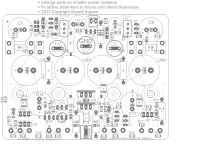
However, in thinking further, I may be able to include filter caps on-board with the Full Monty options by opening up space for them across the middle of the board instead of at the top. The advantage is that it places them closer to where I have already routed the power connectors so I no longer have an issue with the ground return.
Attached is a concept drawing - it is less than 75mm tall so it fits on the preferred heatsink. I've had to restrict the size of these additional filter caps to 18mm diameter (commonly available) which allows up to around 2,200uF per cap at 63V rating but higher values if 50V rated. I may have space to form a CRC filter too.
I'm not sure if this creates any unintended problems yet, I'm a bit nervous about proximity of power supply charging pulses to the input stage - but I'll look further at this option.
Gannaji - I agree, the latefet could be a nice simple amplifier to try. I may return to this later.
Attachments
Last edited:
Hugh, I might just take you up on that offer. I have a work colleague who has your earlier ASKA 55 who has offered an audition too.
Gareth, this is getting better and better! I've looked up some datasheets and the most suitable I could find is the Panasonic KW series 3.3mF with a 2.36Arms ripple rating - quite respectable for this size can.
I would perish the thought of a CRC unless you can somehow magically free up enough space for 25mm caps. The first "C" simply won't have enough Arms to take up the ripple.
Could you remove the existing 330uF caps and in doing so create enough room to increase the size of one or both pair of main caps to 22/25mm? Those that wish to use an off-board supply can simply install 330u caps to these locations.
Member
Joined 2009
Paid Member
Could you remove the existing 330uF caps and in doing so create enough room to increase the size of one or both pair of main caps to 22/25mm? Those that wish to use an off-board supply can simply install 330u caps to these locations.
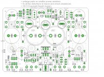
The space taken up by the existing caps, which are 390uF actually (the 330uF is a typo) is not available for the larger caps because of other components and mounting holes getting in the way.
However, I do believe, if I were to squeeze the design to the very limit, I could accommodate one pair of 22mm dia caps alongside one pair of 18mm dia caps. But no way to fit any 25mm or two pairs of 22mm if you want to keep the pcb under 74mm tall.
At 22mm dia you can get 4,700uF at 63V, for example Nichicon LS, with a 3.7A ripple rating.
Attached image - the larger caps show sizes 20mm and 22mm dia overlayed, hence it is the outer circle we're talking about here.
Attachments
Last edited:
lordearl, I typically find RS have a better range and pricing on most items, plus they do free shipping too. I'm happy to put together a BOM for the different build options once the board layout is finalised.
Might even be worthwhile doing a group buy from Mouser if there is enough local interest - particularly if we have the boards shipped to one AU location.
Sent from my iPad using Tapatalk
Might even be worthwhile doing a group buy from Mouser if there is enough local interest - particularly if we have the boards shipped to one AU location.
Sent from my iPad using Tapatalk
Member
Joined 2009
Paid Member
Thanks for the good words everyone.
I appreciate the confidence, but I wonder if you would prefer to see the thing work before you go buying stuff ? Perhaps take another look at the circuit and check that it all makes sense, also question the parts values. Just so we don't rush and make a mistake. I've uploaded the current version of the simulation file I'm using which I find very helpful in exploring parts values and checking to see if the circuit is tolerant to variations.
If you are adept with spice you can help by reviewing the design.
The compensation capacitors usually benefit from some experimentation to fine tune them so it will be wise to have more than one value on-hand. There is a zener diode in the dc-protection circuit that should be sized appropriately for the power supply voltage as this is designed to ensure the current supply to the solid state relay is cut out when the power rails start to collapse - and disconnect the speaker before the amplifier makes any weird turn-off noises.
Looking at the choice for parts at this point does help me with the pcb layout because there are some factors to consider. For example, the hole size for the 22mm cap should be larger if using snap-in than if using regular through-hole.
I can't comment on pricing, but like Hugh, I use Digikey almost exclusively for my own builds.
Attachments
Last edited:
I'm on holiday this week with only a phone, tablet, 3G connection, and rainy weather at our holiday destination. I can work on the BOM when I return this weekend.
Agree we should take our time and double check anything. Having said that I think anyone who wants to be part of the first board order needs to understand the experimental nature. The built boards may play music or may not!
Agree we should take our time and double check anything. Having said that I think anyone who wants to be part of the first board order needs to understand the experimental nature. The built boards may play music or may not!
But no way to fit any 25mm or two pairs of
22mm if you want to keep the pcb under 74mm tall.
Attached image - the larger caps show sizes 20mm and 22mm dia
overlayed, hence it is the outer circle we're talking about
here.
Hello Bigun,
Maybe it is possible to gain some add space if the R40-41 would be
relocated on the bottom side of the PCB - the pads for them should
be holeles just a bit prolonged if the traces connected to them are
also at the bottom side.This way there is gained some space on the
top of the PCB for the 22mm dia caps, now if it is possible to rotate Fuse
holders 180 deg. and moved U$3 and U&4 closer to main 22mm caps and
I hope the gained space will permit the U$3 and U&4 to become 22mm dia caps.
As I can't see the traces on top and bott of the PCB it's just my
guess but You are the ART master and You'll easily check the
possibilities.
And You have the PM please check it.
With my best regards,
A.
Member
Joined 2009
Paid Member
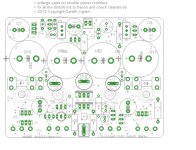
Now that Smiley has thrown down the gauntlet, Bigun *must* find a way to accommodate four 22mm caps all on a 98x74mm PCB
You mean like this ?
It's starting to get into silly territory here though, it will be a fiddly amplifier to assemble, not for the first time constructor.
Attachments
- Home
- Amplifiers
- Solid State
- TGM8 - my best amplifier, incredible bass, clear highs, no fatigue (inspired by Rod Elliot P3a)