I found this interesting. Towards the bottom of the page is a link for a solid state circuit breaker.
Google Translate
Google Translate
So far I am finding that Thick film = metal oxide and that Thin film = metal..............The 1206 resistors I have used before are all (thick) metal film (Stackpole from Digikey), but some folk like to use other stuff. I'll start out with 1206................
Further that Thick film are generally 1% or 5% tolerance whereas Thin film seem to be 0.1%.
That seems to make Thin film very much more expensive than Thick film.
So far I am finding that Thick film = metal oxide and that Thin film = metal.
Further that Thick film are generally 1% or 5% tolerance whereas Thin film seem to be 0.1%.
That seems to make Thin film very much more expensive than Thick film.
Thanks for the info. That's exactly what I wanted to know but the owner of local shop where I buy components was unable to give me precise answer.
Thinking about this some more I don't expect there will be enough room for 4 bulk caps plus pi filters. Can you simply add a couple of pads - one per rail - and leave it at that? 30 or 35mm if there is room or 22/25mm if not. Of course there will need to be room for the fuse clips. It's going to be tight working in the constraints of a 100 x 74 board.
I also noticed in your schematic that you've added an RC filter on the +ve rail for the front end but not negative. Why is that?
People who want to build a beefy PSU will do that off board anyway, as will those wishing to experiment with regulators and cap multipliers. In that case they can install 470uF caps into these locations for local filtering.
Can you reconsider provision of the input cap, even if it a small pad for a film cap of 5mm pitch. There will be people who will want to install a cap and bypass the doc protection circuit, or vice-versa. There will be others who want the extra protection of both. It doesn't occupy much space, gives people flexibility, and is easily jumpered by those that don't require.
Sent from my iPad using Tapatalk
Member
Joined 2009
Paid Member
Hi, I'll give all these good ideas some thought as I work through some of the layout challenges.
The negative rail to the front end is also RC decoupled and it's there in 'plain sight' in the schematic. But you are probably not used to seeing it in this form, it's quite clever - give it a little more thought - can you spot it ? (Hint: the output can be thought of as 'clean' just like the power ground)
The negative rail to the front end is also RC decoupled and it's there in 'plain sight' in the schematic. But you are probably not used to seeing it in this form, it's quite clever - give it a little more thought - can you spot it ? (Hint: the output can be thought of as 'clean' just like the power ground)
Last edited:
C2 appears to be serving double duty as the feedback capacitor and -ve rail filter cap. But I don't understand how or why, nor the rationale for the resistor values around it. Why is C22 necessary?
I can't find much info on Singleton input stages - either in Bob Cordell's book or on the Internet.
I can't find much info on Singleton input stages - either in Bob Cordell's book or on the Internet.
Member
Joined 2009
Paid Member
Well if we look at the -ve rail there are only two items once you get back from the output stage.
Referring to the part numbers in my schematic at post #23:
The nearest item to the output is the VAS, the collector is connected through R27 and R28 to the -ve rail. Connected to the junction between these resistors is the bootstrap cap from the output, which for the purpose of worrying about noise on the power rail is pretty much the same thing as ground since it connects to ground through the speaker. The combination of the boostrap cap C13 and R27 act to isolate the VAS collector from noise on the power rail. It's not as obvious as an RC filter on the rail where the C goes to ground, but it works pretty well all the same. This is what I meant by 'in plain sight' - but not so obvious on first look.
Of course there is also a connection to the -ve rail from the dc bias network (Q14 and surrounding parts) but this is also well isolated from noise on the power rail. First off, by the zener diode. Then you have the resistors R38 & R39 along with C22 which act to form an RC filter. And lastly there's the feedback cap C19 and R41 which also act to prevent noise from entering the feedback node. All this keeps the PSRR healthy.
See attached for more information. Based on this, we want to use the thin film version. Digikey sells them at very good prices. For example, as of today if you want qty 10 of 1k value, they are only 7.8c each.
http://www.digikey.ca/product-detail/en/RNCP1206FTD1K00/RNCP1206FTD1K00CT-ND/2240675
Referring to the part numbers in my schematic at post #23:
The nearest item to the output is the VAS, the collector is connected through R27 and R28 to the -ve rail. Connected to the junction between these resistors is the bootstrap cap from the output, which for the purpose of worrying about noise on the power rail is pretty much the same thing as ground since it connects to ground through the speaker. The combination of the boostrap cap C13 and R27 act to isolate the VAS collector from noise on the power rail. It's not as obvious as an RC filter on the rail where the C goes to ground, but it works pretty well all the same. This is what I meant by 'in plain sight' - but not so obvious on first look.
Of course there is also a connection to the -ve rail from the dc bias network (Q14 and surrounding parts) but this is also well isolated from noise on the power rail. First off, by the zener diode. Then you have the resistors R38 & R39 along with C22 which act to form an RC filter. And lastly there's the feedback cap C19 and R41 which also act to prevent noise from entering the feedback node. All this keeps the PSRR healthy.
So far I am finding that Thick film = metal oxide and that Thin film = metal.
See attached for more information. Based on this, we want to use the thin film version. Digikey sells them at very good prices. For example, as of today if you want qty 10 of 1k value, they are only 7.8c each.
http://www.digikey.ca/product-detail/en/RNCP1206FTD1K00/RNCP1206FTD1K00CT-ND/2240675
Attachments
Last edited:
here is a few things ....
Yet again some of our friends adding their opinion here think EFP while trying to add a valid opinion for a CFP ..That doesn't work very much ....i think ...
What makes the P3A a success is the CFP output stage ,bootstrap,LTP
Trying to repeat the result of single pair of a CFP output will not work by adding a couple of transistors + the stability issues .
As about the mosfet added pair i really don't have an idea how will this sound cannot comment on that farther .
Many know that English is not my native language and between humor and translation it is not always easy to explain what i have in mind but i will try :
I could describe with one word a family of circuits like the CFP or a bootstrap circuit or a one transistor preamplifier /capacitor coupled as a ""free"" or ""floating"" circuit that can be easily part /hfe depending , part quality depending , higher in distortion , but in total more friendly to the ear and probably including some errors due to the simplicity of circuit ...
A more proper description could be that a circuit like the ones mentioned above will have its own behavior regardless of physics and simulator laws producing a specific result take it or leave it . Still circuits like described above will have a tension to follow music better than following laws of physics and simulators .
Trying to fight the mentioned problems by adding a full VAS , a diamond input, an EFP output will make physics far too happier , will eventually make calculations on simulator or paper to work far better , plus that EFP with a good calculated dual VAS ,or a proper diamond in the input is far too forgiving in any other mistakes you will make ...
The result though even though might calculate better, simulate better,and have a better electrical static result in the end will have absolutely nothing to listen regarding the specific character added by the description of circuits above .
Closing Argument
--- An amplifier that has CFP output stage , with a bootstrap on the VAS , and a singleton input stage , to my ears sound very scary .... too many stages on the amp will work on their own and i expect the result to be totally out of control so for me its a NO
---CFP output stage will not repeat the characteristics of the amplifier and increase load tolerance and power together with increased rails if more outputs are added .That is EFP thinking and will not actually work in a CFP design ( or it will work in the order to produce more current in the output but eventually you will loose many of the characteristics of the amp in the process of stabilizing the amp ) So this one is also NO
---As about the mosfets in the output my knowledge is not enough to predict both the Current behavior and sonic performance .
That was my opinion ...I actually admire Bigun for putting effort of that level in the circuit ( and many other circuits ) I placed my opinion for the record and i trust that many of our friends here with better knowledge than me will comment and evaluate properly both my thoughts and Bigun's ideas
Kind regards
Sakis
Last edited:
Member
Joined 2009
Paid Member
Andrew, can you point me to a text that deals with the Singleton IPS? I can't find any reference to it in Cordell's book, and scarce material on the Internet.
Hi,
One place with some introductory comments is here: Elliott Sound Products - Audio Power Amplifier Design Guidelines
If you dig a bit deeper you will find a lot more. JLH is a famous Brit that advanced the art of solid state amplifier design early on and was often to be seen using the Singleton input. Try searching for the jLH 1969 Class A amplifier.
Closer to your part of the globe would be Hugh Dean of Aspen Amplifier / ASKA fame. He has also built a lot of well designed amplifiers that achieve that distinction of being well engineered and also tuned and optimized for great sound - he also favours the singleton input these days.
You can of course take the singleton into the symmetric design realm, Jean Le Hiraga is well known for his Class A amplifier which uses this approach and there is a whole thread on this forum that is currently very active talking about 'CFA' - meaning 'current feedback amplifiers'. The singleton is a form of CFA to many people.
At the end, there may be only subtle differences between a singleton and the LTP. It's part of the fun of this hobby to explore these differences.
Many know that English is not my native language and between humor and translation it is not always easy to explain what i have in mind but i will try :
Kind regards
Sakis
Hi Sakis - your English is very good - we are very happy to have your contributions here as you are an expert on the P3a.
Please don't worry about the MOSFETs, for purposes of understanding my design consider them not to exist - the amplifier assembled without them. Only real difference here is the Singleton... which makes you a little nervous I see

Last edited:
Member
Joined 2009
Paid Member
Thanks MIIB, it feels good to receive positive feedback.
Hi Ranchu32, Prototype ? - life's too short for that (actually my day job makes me far too busy) but if somebody else wants to prototype it before I finish a pcb layout that would be marvelous, if not we're going to rely on our good design skills to get it right first time. I think we're up to the challenge ! I'll start designing a pcb this weekend and hopefully get it done in a week or less. Then I'll send it off for fabrication in China. I hope a few eagle eyes (did you notice the play on words there ?) on this forum will help error check it.
Hi Ranchu32, Prototype ? - life's too short for that (actually my day job makes me far too busy) but if somebody else wants to prototype it before I finish a pcb layout that would be marvelous, if not we're going to rely on our good design skills to get it right first time. I think we're up to the challenge ! I'll start designing a pcb this weekend and hopefully get it done in a week or less. Then I'll send it off for fabrication in China. I hope a few eagle eyes (did you notice the play on words there ?) on this forum will help error check it.
Every good audio subjectivist should check out JLH's designs and others collected by Paul Kemble. JLH's books are still quite expensive but there is enough illustration and educational pointers in these pages to keep a DIY active for many years. Of course , there are singleton designs there too. A Paul Kemble web page - JLH mosfet amplifiers.If you dig a bit deeper you will find a lot more. JLH is a famous Brit that advanced the art of solid state amplifier design early on and was often to be seen using the Singleton input......
Also, The Class-A Amplifier Site
is a good source of JLLH circuits.
And also a good selection at http://www.keith-snook.info/wireless-world-magazine/wireless-world-articles.html
is a good source of JLLH circuits.
And also a good selection at http://www.keith-snook.info/wireless-world-magazine/wireless-world-articles.html
Last edited:
Every good audio subjectivist should check out JLH's designs and others collected by Paul Kemble. JLH's books are still quite expensive but there is enough illustration and educational pointers in these pages to keep a DIY active for many years. Of course , there are singleton designs there too. A Paul Kemble web page - JLH mosfet amplifiers.
Yes, Paul Kemble is a gold mine of relevant schematics and practical information about amp construction.
I have been tempted... and fitted a somehow different output to the PA3 Variant a bit HOOD like and then not at all...
I have also been tempted to try and work with cherry style nested compensation.
I have servoed, but this does also alter the input offset SO I am not really sure if its a workable solution.
I believe that when you have no input cap you need a servo to absorb any DC offset of your sources. I normally set my servo so it can absorb up to 0.25 V
. I have also been tempted to try and work with cherry style nested compensation.
I have servoed, but this does also alter the input offset SO I am not really sure if its a workable solution.
I believe that when you have no input cap you need a servo to absorb any DC offset of your sources. I normally set my servo so it can absorb up to 0.25 V
Attachments
Last edited:
Member
Joined 2009
Paid Member
If I have time I'll consider it - feel free to remind me later. The first version though will be split rail, it's likely to be too difficult to accommodate both on the same pcb.Bigun,
Can I request for a 'Single Supply variant of this TGM 8' for us retros?
I believe that when you have no input cap you need a servo to absorb any DC offset of your sources.
It depends on the amplifier and the source. I have seen many people report that the input cap is critical and so small on-board caps can be a compromise. As a result, you need to allow lots of board space for high end film caps. Or you mount them off-board. The SKA GB150 by Greg has space for a small on-board cap and most people don't install it.
In the P3a and this TGM8 the feedback network has a capacitor to ground to ensure 100% feedback at d.c. This means that any dc offset at the input is not amplified. A small amount of dc offset at the input = small dc offset at the output which I don't worry about. As my source components often have output capacitors I already have a dc-block in the signal path and I hate to spend big $ on high quality input caps for an amplifier when there should already be one at the source. So I don't use input caps in most of my amplifiers anymore.
---
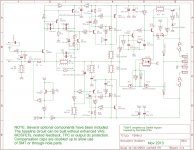
Well - I'm attaching the Eagle schematic. DON'T PANIC - it looks rather complex I know. This is because it includes ALL the options I have been thinking about (including an enhanced VAS you probably haven't seen before anywhere else and my design for a solid state output relay with delayed-on and fast-off you also probably haven't seen before anywhere else). It allows me to see what I can fit on the pcb and what I can't. Anybody interested in building TGM8 - YOU WILL BE ABLE TO ASSEMBLE THIS AMPLIFIER IN IT'S SIMPLEST FORM leaving many parts off the pcb and adding a couple of links where needed. I've determined which resistors need to dissipate reasonable power and have shown them as 'glowing resistors' on the schematic. I am going to favour through-hole parts for these resistors and SMT for the rest.
Now would be a good time for people to chime in with any errors you can see!
Attachments
Last edited:
- Home
- Amplifiers
- Solid State
- TGM8 - my best amplifier, incredible bass, clear highs, no fatigue (inspired by Rod Elliot P3a)