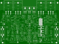
Well actually this is for reference only maybe good or bad ideas that I have been done for the pass 2 years, I'm not an expert but I still learning here are example of some layouts I've been making for a long time the last one I did is Dx Super A and I'm happy with the results, a few days ago some one told me that this is not about brands or make small or too neat or aligned is about create a functional layout that is mechanically correct example I've been reading the thread of "Honey Badger" and mister OS he knows what he was doing there is a lot of planning concerning avoid oscillations, parasite capacitance, the correct traces thickness there is more to it but let's leaved simple, so it opens my eye that is not about size, neat or
"fancy macros"
is about a correct well planed design that can perform with no layout problems.
I did learn electronic in the US Army but was not about designing stuff was more about repairing stuff in the field my MOS was 94F "Special Electronics Device Repair" so nothing about designing stuff only repairs, is "go or no go"
any way I will leave this images so you guys can see some good some wrongly made,but this my help others to understand that is not an easy task it needs planning and cost budged and all that good stuff.
Also the only software I use is Sprint Layout 5 and I have been use it for about 2 years, I know they are more better software that have more options
but for audio amplifier PCB designs is fine for me I have plans to buy the new version 6 but I'm afraid that files from 5 will not work with the older version let see what might happen , ok so I will share macros designs simple stuff I will arrange them in categories resistors, heat sinks, diodes, transistors, others,.
Maybe I will make simple tutorials about making new macros and some other information.
I will leave the images here maybe this will give you ideas sometimes we have the knowledge to create something and we do not have the puzzle resolve. ok guy have a wonderful Halloween have fun but do not eat too many candies jejejeje have fun
Regards
Juan
"fancy macros"
is about a correct well planed design that can perform with no layout problems.
I did learn electronic in the US Army but was not about designing stuff was more about repairing stuff in the field my MOS was 94F "Special Electronics Device Repair" so nothing about designing stuff only repairs, is "go or no go"
any way I will leave this images so you guys can see some good some wrongly made,but this my help others to understand that is not an easy task it needs planning and cost budged and all that good stuff.
Also the only software I use is Sprint Layout 5 and I have been use it for about 2 years, I know they are more better software that have more options
but for audio amplifier PCB designs is fine for me I have plans to buy the new version 6 but I'm afraid that files from 5 will not work with the older version let see what might happen
, ok so I will share macros designs simple stuff I will arrange them in categories resistors, heat sinks, diodes, transistors, others,.Maybe I will make simple tutorials about making new macros and some other information.
I will leave the images here maybe this will give you ideas sometimes we have the knowledge to create something and we do not have the puzzle resolve. ok guy have a wonderful Halloween have fun but do not eat too many candies jejejeje
have fun Regards
Juan
Attachments
-
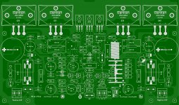 Dx Super A Sanken.jpg835 KB · Views: 1,782
 -
 Logos.jpg73.7 KB · Views: 1,521
 -
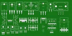 transis.jpg415 KB · Views: 1,460
 -
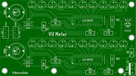 VU meter.jpg244 KB · Views: 1,393
 -
 Mazinger Z.jpg904.7 KB · Views: 1,435
 -
 Dx Super A large.jpg608.4 KB · Views: 867
 -
 Mazinger Z 2.jpg902.6 KB · Views: 693
 -
 Minerva X.jpg483.4 KB · Views: 690
Last edited:
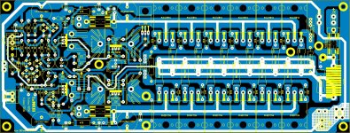
Where is the schematic for the 5 pair layout with plus and minus 90 volts?
You work is phenomenal, very good.
Thanks
Oh well that is 6 pairs but the schematic belong to Carlos Dx Blame MKIII is not tested or approved by Carlos I posted as example not really a diy project
I was having plans to make it but I still got to check for errors so did you like it wow I thought nobody will like it jejejejeje
thanks for the comment Regards
Juan
hey buddy good to see you here you are welcome to post ideas too every one can participate
Regards
Juan
Many thanks bro....I hope many diyers will share some advance design layout techniques too...
nice work indeed..those symbols (the scorpion..)how did you make the scorpion? is it a macro for sprint layout 5?can you share it?or at least describe the process of creating such symbols?
Is there a way to import external symbols and drafts to a macro?
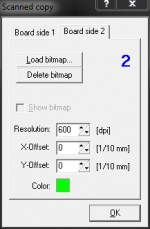
Actually yes you can take a bitmap image and placed in the back of Sprint Layout 5 and just fallow the lines but grid has to be really small too just import bitmap image but remember it has to reduce so it will be not too big.
Regards
Juan
just import bitmap image but remember it has to reduce so it will be not too big.Regards
Juan
Attachments
Last edited:
Maybe there could be a thread for the basics of layout of Power Amps. Especially for doing power and ground layouts. Maybe even one for Ground Planes.
I there is any will be nice to be here in this thread thank you
Regards
Juan
nice work indeed..those symbols (the scorpion..)how did you make the scorpion? is it a macro for sprint layout 5?can you share it?or at least describe the process of creating such symbols?
I will make another video about create custom symbols is a good way to separate your designs so piracy can not touch your work
Regards
Juan
Yesss....that would be very helpful coz layout is mandatory in every diy amplifiers and more thank you....
voted for 5 star...
Regards,
thanks Willy
Regards
Juan
- Status
- This old topic is closed. If you want to reopen this topic, contact a moderator using the "Report Post" button.
- Home
- Amplifiers
- Solid State
- Dx Juan layouts ideas PCB