Here is my work in progress. I thought I'd share this too.
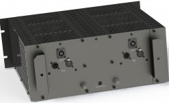
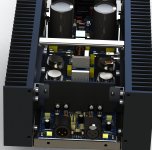
Based on the leach amp, just slightly modified. 3 output pairs of MJ15003/4. input changed for balanced input on XLR plugs with no wiring. Protection circuit and power supply on one single board. The goal is to reduce wiring to the strict minimum possible. The toroidal transformer is right below the pcb and it's wires come straight to the pcb. A power on delay also sits below the pcb near the transformer. The case and mains power cord is the only thing linking each amp, as each amp is a totally independent module.
Based on the leach amp, just slightly modified. 3 output pairs of MJ15003/4. input changed for balanced input on XLR plugs with no wiring. Protection circuit and power supply on one single board. The goal is to reduce wiring to the strict minimum possible. The toroidal transformer is right below the pcb and it's wires come straight to the pcb. A power on delay also sits below the pcb near the transformer. The case and mains power cord is the only thing linking each amp, as each amp is a totally independent module.
Attachments

Dude your software rendering is so realistic ")
Here is my work in progress. I thought I'd share this too.
Based on the leach amp, just slightly modified. 3 output pairs of MJ15003/4. input changed for balanced input on XLR plugs with no wiring. Protection circuit and power supply on one single board. The goal is to reduce wiring to the strict minimum possible. The toroidal transformer is right below the pcb and it's wires come straight to the pcb. A power on delay also sits below the pcb near the transformer. The case and mains power cord is the only thing linking each amp, as each amp is a totally independent module.
Dude your software rendering is so realistic
It's bluffing ain't it?
Nice to be able to fully design and visualize everything before actually making it.
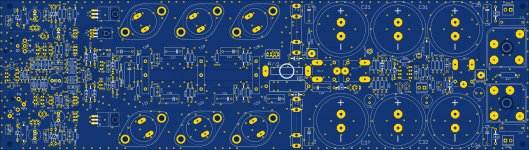
Here's the pcb and sch:
Attachments

It's bluffing ain't it?
The first 3 pictures look real to me.
The first 3 pictures look real to me.
That's the idea behind "rendering". I made them in high res so I could get the best feel possible and life like.
I am doing the design from the pcb all the way to the case in every detail, so then it can be built with all the proper parts professionally manufactured. I have a good contact in china who can make all this metal stuff properly, with the laser cutting table and the whole shebang. I only need to find a good place to get the screen printing done. I will also have the aluminum parts anodized black, in the same way the heatsinks are, for a good overall impression. The theme is black, with most parts, including most screws in black color.
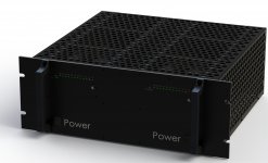
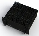
I want the amp to "breathe" and not enclose its heatsinks in an airtight case. So that's the reason why the case is full of holes. Plus there is plenty of space below the amp modules for the air to circulate coming from the sides and going up in the center in case the amp is sitting on a flat surface instead of a rack. I didn't show the feet on those renderings, but there are 4 rubber feet below, which add a little more space for airflow.
It's not forced cooling, so the convection must not be hampered too much, and I think with the oversized heatsinks, the cooling should not be an issue.
Those heatsinks are the SK479 from Fischer. I carefully chose each part of this design.
I am designing it so some variations can be made without having to change everything. For example I plan to make a stronger version with higher rails and more powerful outputs. which would use 2 toroidal transformers, with the same power-on delay and everything about the case would remain the same.
That existing design with the MJ15003/4 can easily be changed for the MJ15024/25 or MJ21193/4 for example.
I want to avoid "exotic" semi, so the japanese transistors aren't an option.
Everything that you see on these pictures has been DIY'ed:
-Amplifier based on LME49810 power amplifier driver. (PCB layouts done by myself).
Output stage-3 pairs matched NJW4281 & NJW4302 ON semi.
-The power source is a full-bridge power converter based on ETD49 core.
+/-60Vcc 800W. (PCB layouts done by myself)
- The aluminum case done by myself.
Very easy to work with this LME driver and the sound astonish in a pleasant way.
Unfortunately, I made a mistake with inscription from front panel.
Clip left is repeat twice. This is it.
Look great! But I prefer the black theme!
I want the amp to "breathe" and not enclose its heatsinks in an airtight case. So that's the reason why the case is full of holes.
looks great, and I like the idea
but it is also a somewhat dangerous design
might be a good idea to put a lid on the heatsinks of each amp module (inside the vented box)
more on work in progress
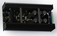
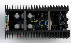
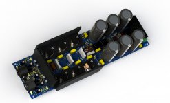
Posting a few more renderings.
This is just one module. 2 modules in the case, 100% separate, all the way to the power cord.
Posting a few more renderings.
This is just one module. 2 modules in the case, 100% separate, all the way to the power cord.
Attachments
looks great, and I like the idea
but it is also a somewhat dangerous design
I don't see how this could be dangerous in any way. Can you explain what you mean?
might be a good idea to put a lid on the heatsinks of each amp module (inside the vented box)
The heatsinks are at ground potential, galvanically isolated from the DC in the amp, no voltage applied to them, so there is no issue there, and no hands can go inside touching the transistor cases, which do have potentially lethal voltages, unless someone purposely opens the case and goes fooling around inside, but then there is nothing to do about such stupid behavior.
is it for professional use ?
Can easily be. The case is designed for rack mounting and the heatsinks oversized with extra room below for airflow in case someone puts it on some flat surface, table, flycase, etc...
The goal is a reliable, stable amp that will stand up to abuse, so I guess yes, it's aimed also at pro usage.
might be a good idea to put a lid on the heatsinks of each amp module (inside the vented box)
There is a lid, full of hole, just because it must breathe. There is heat to evacuate all over and the more air flows, the better. It would be a pitty to block that air flow.
Now if you are thinking about someone dropping some tiny metal part through the vent holes on top of the pcb, then it's true this could cause an issue, but who would find something that small and metal, that could pass through those holes, and who would go drop it there? Unless it's done on purpose, I don't see why this would happen in normal use.
Plus, why also block the view from all that electronics inside? That too is a sight that I like in the amp. Seeing the guts of it is a plus to me
I don't see how this could be dangerous in any way. Can you explain what you mean?
Now if you are thinking about someone dropping some tiny metal part through the vent holes on top of the pcb, then it's true this could cause an issue, but who would find something that small and metal, that could pass through those holes, and who would go drop it there?
that was my main concern, yes
imagine yourself bending over your amp, and dropping a small solder bit from your clothing
when using amp for PA/instrumnet I might have a bad habbit of placing various things on top of it
but could be anything really ... never dropped a component, like a resistor, or a screw ?
anyway, venting would not be limited, but maybe even improved
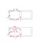
here is what I 'expect' the convection will look like, with and without the 'inner sub lids'
its about controlling air flow to avoid possible turbulent chaos
Attachments
here is what I 'expect' the convection will look like, with and without the 'inner sub lids'
its about controlling air flow to avoid possible turbulent chaos
I see what you mean, but then the central area above the pcb would no longer have convection and would be enclosed.
Only a "hacker" messing around with tools and soldering iron over the amp could drop something in those vents. I doubt in the field when putting amps in a rack and during their use there would be any chance of small bits of metal falling inside the amp. It's so unlikely that I would prefer leaving the air flow than block it from flowing.
I've seen so many diyers making good looking layouts, big heatsinks, and then enclose the whole thing in some wooden box with hardly any air circulation...
In this design, I make use of the inner room to have double the heatsinks. Of course the convection won't be the same between the inner sinks as it is for the outter sinks, but I think this should work anyway. Short of going forced convection, this overdesign should ensure some level of reliability. As long as any pcb layout related considerations have been addressed.
I want to aim for the best layout possible, so I am open to suggestions that help in all respects this layout.
I see what you mean, but then the central area above the pcb would no longer have convection and would be enclosed.
no, you could have increased airflow coming through the ends of each amp module
but basicly, route the air between the heatsink towards the top of heatsink, and the air escaping there will increase the outside airflow at fins
and that is also where it really makes a real difference
the inner side of the heatsink is not very effective, only the fins are
so basicly you want the inside 'trapped' air to escape such that it 'supports' the outside airflow
but ok, its very cool
no, you could have increased airflow coming through the ends of each amp module
There is no gap at the end of the modules on the input side, as the edge of the module butts against the back plate, for the XLRs to poke through. And on the front side near the vu-meter, the gap is small, mostly to let the few wires from the transformer come through and leave a little air come in to cool the small heatsink placed on top of the rectifier bridges. The distance between the ends is about 40cm, so that is a very long way for air to flow.
I'll output a top view of that area so you understand how it's layed out inside that case...
There is a lid, full of hole, just because it must breathe. There is heat to evacuate all over and the more air flows, the better. It would be a pitty to block that air flow.
Now if you are thinking about someone dropping some tiny metal part through the vent holes on top of the pcb, then it's true this could cause an issue, but who would find something that small and metal, that could pass through those holes, and who would go drop it there? Unless it's done on purpose, I don't see why this would happen in normal use.
Plus, why also block the view from all that electronics inside? That too is a sight that I like in the amp. Seeing the guts of it is a plus to me
I like your amp! But, as mentioned before, I would not use that top cover with that "much" ventilation
. I know ventilation is good for the amp, but that much is bad.How bad? Well it is not only that some kind of metal can go inside by mistake, But also water or any liquid too...ooh and do not forget that "dust" is a bad thing for electronics too and with that much ventilation it will be easy to accumulate dust inside. if you want to see the guts inside your amp....well take a few pictures
.Do not take it wrong, it is a recommendation only...at the end it is your amp and you can do anything you want to it
. if amp is well design, the "only" parts that will be hot when it is in use will be the heatsinks and those have to be very well ventilated. My amp is completely sealed and the heatsinks are located on the outside so ventilation is very good and I do not have to worry about dust or liquids splashing inside amp. I would like show the guts of my amp and leave the cover off, but I know it is a bad idea!.I like your amp! But, as mentioned before, I would not use that top cover with that "much" ventilation
How bad? Well it is not only that some kind of metal can go inside by mistake, But also water or any liquid too...ooh and do not forget that "dust" is a bad thing for electronics too and with that much ventilation it will be easy to accumulate dust inside.
I agree for the dust issue, but for the liquids and even food issues, I see that some are working around amps and other such equipments with a beer in their hands and maybe eating food while working on them...
That has never been any issue for me and anyone around me, as I would never never be drinking and eating while doing this stuff.My amp is completely sealed and the heatsinks are located on the outside so ventilation is very good and I do not have to worry about dust or liquids splashing inside amp.
If you're carrying food and drinks around your amps, that's a concern.
I wanted more heatsink, and I could not put them in such an arrangement with only one sink on each side. This is the classic way of doing it, it's been done for ever...
I would like show the guts of my amp and leave the cover off, but I know it is a bad idea!.
Why a bad idea? Do you have a beer in your hand right now???
Better safe than sorry!
I fixed many amps in the store where I worked and some of them got broken because of the accumulation of dust that shorted out parts inside. Dust plus humidity....it is bad
I had some that had liquid damages (parties, accidents).
I am not saying that your amp will brake because of the "open" chassis, but you should always think the worse case scenario.
PS: I remember one amp that had a lot of dust inside (most parts were under dust) and when I checked the DC offset, it was very high, I vacuumed all that dust. after the boards were cleaned, I checked the bias and Dc offset and guess what?.....all readings came back to original specification
Better safe than sorry!
Hee hee, right you are!
I fixed many amps in the store where I worked and some of them got broken because of the accumulation of dust that shorted out parts inside. Dust plus humidity....it is bad
No kidding!!! I have 2 amps right now that I won't even dare plugging in.
Those amps were sitting unused in a basement (moist) for a good 15-20 years. They are the solid types from the 80s, they don't build them that way any more. Strong amps, robust, and they are enclosed as you mentioned, but the dust and mostly moisture got into them and they are rusted all over the place. Those need a lot of restoration work, but should work again with some TLC!!!
I had some that had liquid damages (parties, accidents).
I am not saying that your amp will brake because of the "open" chassis, but you should always think the worse case scenario.
Yes, perhaps if they were to be sold on the open market, they could end up being subjected to such stupid abuse. This won't be the case right now, as they're not meant to be sold that way. It's for diy build and usage, and some changes can easily be made in that respect by those who would want to protect against such possibilities.
Even thought they will be used in PA type settings, in a pro environment (discotheque possible) or at least in a semi-DJ type of use, they are not aimed at the average idiot who knows nothing about electronics.
PS: I remember one amp that had a lot of dust inside (most parts were under dust) and when I checked the DC offset, it was very high, I vacuumed all that dust. after the boards were cleaned, I checked the bias and Dc offset and guess what?.....all readings came back to original specification
I bet!! I worked on some pcbs in a factory, although they were brand new, just made and soldered, some dirt can sometimes come in and ruin the fun. A simple cleaning with freon (no longer available
) cleared up issues too...- Status
- This old topic is closed. If you want to reopen this topic, contact a moderator using the "Report Post" button.
- Home
- Amplifiers
- Solid State
- Work In Progress... Leach Based Amplifier