If that is a protection relay, it looks totally inadequate with a contact
rating of 7A/ 30VDC for such a powerful amplifier.
Yes, and I put 2 in parallel for good measure.
I looked at many models and I didn't want one too big in there.
If you have a better one to suggest, I will take a look at it. Not too big though.
I will still use 2 in parallel in any case. And there is one other for the mains power detection, I kept the same model to make things easier. I am considering adding one more for muting the input, but that takes so much room, I'm more interested in using a solid state switch like the J111/112. But this may be for a future version, maybe when I make use of the flat packs, which will take up less pcb real estate and that will allow more stuff on that precious space.
The Lo Tim uses 2pair of 250W 175°C To3 devices.I am wary of the flat packs when it comes to power dissipation. You need a larger number of them compared to the metal cases.
Eventually I will make a version of my design with flat packs, as they are more convenient and easier to mount on heatsinks. Plus we can design for a forced cooled tunnel heatsink and that is one of my plans for the bigger amps for my low frequency speakers.
I used 3pair of 230W 150°C To264 plastic packages to ensure I got Tj about 25C lower than for an equivalent 175°C To3 device.
You have to run the plastic package cooler, as well as allowing for less heat flow through the Thermal interface.
Two relays in parallel do not help with longevity of the contacts, nor does it help with preventing burning/welding of the contacts on opening.
Paralleling helps with reducing the impedance across the contacts and the connecting wiring.
The problem, even with a dual contact relay, is that one pair of contacts opens before the other pair. The time difference only needs to be in the microsecond range and the last opening contact then suffers the burning as the arc establishes across the tiny gap that is just starting to open. It is getting that arc extinguished, that becomes the priority.
Two relays in parallel do not help with longevity of the contacts, nor does it help with preventing burning/welding of the contacts on opening.
Paralleling helps with reducing the impedance across the contacts and the connecting wiring.
I was thinking about the impact on the damping factor, which is reduced somewhat by having less added resistance. Plus since the relay's contacts have insufficient current handling, it doesn't hurt to parallel them. But If there are better relays that can be used, of course I'll take a look at them, but I want to avoid the huge ones though.
They need to be fast to release, if possible, so they are better protection.
The problem, even with a dual contact relay, is that one pair of contacts opens before the other pair. The time difference only needs to be in the microsecond range and the last opening contact then suffers the burning as the arc establishes across the tiny gap that is just starting to open. It is getting that arc extinguished, that becomes the priority.
I think an input muting relay would be nice, if it mutes first before the output relays open. And the use of the output relays for emergency protection is rare, so if we hardly make use of them to switch off while loaded, then it should be too much of a problem. The key is to design so they are not routinely stressed.
Those relays are rather cheap too and easy to get.
Any good relay suggestion is welcome.
I recalculated the protection resistors values for higher value to reduce dissipation, mostly in R26/34 and D3/4. The current in D3/4 was about at maximum when acting for protection or near clipping. The needed power handling for R26/34 was high, requiring bigger resistors. The 1W resistors should now suffice.
I am considering the option to use a solid state muting switch on the input. I've seen the J111/112 types used a lot in such situations, it's simple and should work. I wouldn't place it in series with the signal path, but it can short a resistor when muting.
I am considering the option to use a solid state muting switch on the input. I've seen the J111/112 types used a lot in such situations, it's simple and should work. I wouldn't place it in series with the signal path, but it can short a resistor when muting.
Attachments
Here is one of the relays I considered before going with the songchuan:
Invalid Request
It does have more current capacity, but it's also bigger.
Invalid Request
It does have more current capacity, but it's also bigger.
Re-wire your XLR sockets.
PIN1 goes to Chassis right next to it's respective socket. NOT to Signal Ground.
You're quite right! (as always
 )
)And now that I looked at it, for an unknown reason, I had also swapped pins 1 with 3. Duh!
The thing is, now I'm not sure what I'll do those pin1, because I can't connect that to the pcb ground plane, neither to the signal ground, and there is no easy physical way to connect it to the chassis. And there is the matter of the external ground connection, not an actual pin in the plug, but the plug casing pin, which I had hooked via jumpers to the choice of signal ground or main ground plane. This isn't good now. I will need to change all this.
More changes will be coming real soon on this ongoing design:
- I will do away with the output relay and replace that by SSRs. I am still pondering on that change, as I really think cutting the ground side speaker return is a good idea, but at the same time, the amp output side should really be also cut, so perhaps doing both sides might be nice.
- I will also do away with the fuses on the rails and use SSRs instead, probably triggered by the same signal as the output switches, not certain yet, but seems like a possibility.
- I may remove the zobel from the main pcb and move it to the speaker plug itself, although this is an uggly wiring to do... I may end up with 2 zobels, one on the amp's output before the output R//L and the other farther out on the plugs. I may even think about tapping the feedback on the outer side of the R//L, so that would be included inside the loop.
- I am also looking at an input muting, which I would want triggered in the proper order when muting the output. I definitely don't want to use the VI limiter's trigger to trip the amp's protection on the SSRs, as I don't want a simple soa trespass to stop the show.
This amp is kind of like my test bed for tweaking design choices. Then subsequent versions will probably go further, and eventually those will be using the flat packs.
Hi spookydd
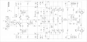
Looking at all these massive preparations and renderings you've made for this classic LTP/VAS topology, my suggestion would be to do some more research among DIY-ers who already have experiences with this amp and ask them would they still choose or recommend this sch or direct you elsewhere. I think such a great project deserves to have deep second thought. All the best
Looking at all these massive preparations and renderings you've made for this classic LTP/VAS topology, my suggestion would be to do some more research among DIY-ers who already have experiences with this amp and ask them would they still choose or recommend this sch or direct you elsewhere. I think such a great project deserves to have deep second thought. All the best
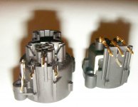
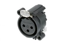
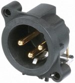
Here are the XLR plugs that I will be using (attached).
Those were not the exact types that I intended using, as I wanted the ones without the extra 4th pin on the plug cases.
I have those, unfortunately, so I have to handle those extra pins. And I figured I would allow for the choice via a jumper to tie them to sig-gnd or gnd. However this isn't any more adequate than tying the pins 1 to gnd or sig-gnd.
Those plugs being mounted on pcb, have no easy way to wire them to the chassis, except perhaps, now that I've noticed it, via the screw hole on the male plug. That screw hole has that inner wire going to that 4th pin, so it would tie to chassis automatically with the screw.
The female one doesn't have that and the 4th pin only goes to that little tab inside the plastic plug that will touch the male plug when it's inserted in it.
There is no easy way to tie the pins 1 directly to chassis, but what if I used the chassis connection coming from the screw on the male plug, tied it on the pcb with the 4th pin on the female plug, and then tie both plugs' pins 1 to this as well, without tying any of them to either sig-gnd or gnd? Or perhaps I could leave the jumpers to chose if we want to tie this chassis local net to either grounds or not at all.
It's probably never good to tie them to either ground, so I guess the jumpers are not warranted.
Attachments
Hi spookydd
Looking at all these massive preparations and renderings you've made for this classic LTP/VAS topology, my suggestion would be to do some more research among DIY-ers who already have experiences with this amp and ask them would they still choose or recommend this sch or direct you elsewhere. I think such a great project deserves to have deep second thought. All the best
I think there is nothing wrong with this schematic, it's the leach amp and although I am making a few minor alterations, I like the leach amp the way it was designed.
If you know of a better design out there, I'd be curious to look at it. So far, there aren't many design coming anywhere close to this leach amp. And I'm not into class A, no tubes and I don't like mosfets, except I will make use of mosfets as protection switches.
There is nothing wrong with this sch, not at all, maybe a little obsolete, just saying such project deserves to persuit the best sound quality possible. My suggestion would be to look into dado's thread of 200 W CFA amp.
There is a lot to catch up there on those threads, but I think most are going for mosfets and that's not what I'm aiming for.
There is one thing that I do favor, it's the low TIM, and those looking to get ridiculously low THD with 3 or more zeroes after the dot, are not paying much attention to TIM. High slew rates can be impressive and open loop bandwidths very high, but I don't believe the high open loop gain and a high feedback are good for low TIM.
Leach's topo may be a little old, but I don't think of it as obsolete and I haven't yet seen anything out there that can be much better. The big buzz words don't make an amp good!
Spooky, There seems to be no middle ground in the CFA vs. VFB argument. It's an argument that borders on religious fervor if you read some of the threads. Lazy Cat has given us a nice little amp in the CFA side. Very simple to build and sounds very good according to others who have built it.
The Leach amp is a very old design, but it still sounds very good to my ears with the modern devices you propose. I hope to have a CFA amp (F5T-Version 2 Cascoded) completed by the end of the year and compare it to my Leach. Of course that involves a lot of changes from the Leach - going from all BJTs and Class AB output to jfet input and Class Amosfet outputs, so it will be hard to tell what audible changes (if any) are related to the topology and what is related to the devices and bias conditions.
Perhaps you could make a board for dado's CFA amp that would fit your current mounting spec. If the PSU is separate (I know you hate wires, but...) the additional cost is for another amp topology to listen to would be minimal.
While I agree with Lazy Cat that given the effort and expense you are investing in your amp you should go for the the best sounding amp possible, I am inclined to let you decide what is the best sounding amp. Don't skimp on parts so you won't second guess yourself later.
There seems to be no middle ground in the CFA vs. VFB argument. It's an argument that borders on religious fervor if you read some of the threads.
I haven't read everything yet, there is a lot there and I don't have that much time to spend on reading for now, but it's true the arguments are more of a personal perception nature and I'm thinking maybe not always based in facts.
Lazy Cat has given us a nice little amp in the CFA side. Very simple to build and sounds very good according to others who have built it.
I'm sure good amps can be made that way as well, but better? that's of a personal interpretation mostly.
Some love and swear by mosfets and don't want to go back to bjts, but I prefer the bjts personally and have no interest in using mosfets or anything like them for sound, although I am definitely now about to use them as switches (SSRs).
The Leach amp is a very old design, but it still sounds very good to my ears with the modern devices you propose.
I see nothing wrong with it at all and I can't wait to get this one working.
Having many more to make (for my 4 ways active) and this first one isn't even going to be used for what I have in mind, I don't see any good reason for now to switch to any other topo. A friend of mine is already interested in this current amp, so it will very likely end up being his and I will continue making more.
I know the way I'm designing it it may be a little "large", but not so much, it's a 4U rack mountable and I've seen so many odd shaped amps made by diyers on the forums that are even bigger. I also know it will be rather heavy, but then again, most powerful amps are unless they're built with exotic power switching supplies and advanced topos like classH/G or even to good old crown grounded bridge.
I want this amp reliable, so it could be used full blast without fear, perhaps in PA although not really suitable for touring because of the size and weight. And I want to make the best sounding one that I can, so I don't think I'm making a bad choice of topo.
I hope to have a CFA amp (F5T-Version 2 Cascoded) completed by the end of the year and compare it to my Leach. Of course that involves a lot of changes from the Leach - going from all BJTs and Class AB output to jfet input and Class Amosfet outputs, so it will be hard to tell what audible changes (if any) are related to the topology and what is related to the devices and bias conditions.
Are you saying that you plan to use the leach as a base and alter it to that other topo?
That sounds interesting, although using the mosfets doesn't interest me, I'm curious to find out what comes out...
Perhaps you could make a board for dado's CFA amp that would fit your current mounting spec. If the PSU is separate (I know you hate wires, but...) the additional cost is for another amp topology to listen to would be minimal.
Sure! That's no problem, it's a lot of work and it takes time, but that's what I love to do, so I will definitely be interested in this.
While I agree with Lazy Cat that given the effort and expense you are investing in your amp you should go for the the best sounding amp possible, I am inclined to let you decide what is the best sounding amp. Don't skimp on parts so you won't second guess yourself later.
Well, as I mentioned before, this one is a first shot, so to speak. I haven't yet built a leach amp and I'm very eager to hear this one. And I'm making it to use the parts that I have on hand as much as possible. But I also have a bunch of MJ15024/5 to use next, and then a few pairs of MJL21193/4.
The case design is made with all this in mind, so without any changes to it, I can use any amp design.
The heatsinks are beefy and I think should work on any config I can come up with, even the flat packs. I will only have to change one part to fit some versions into that case, which is the main pcb support plate, that doubles as a shield as well. I prepared that support plate to be used for 2 toroid transformers for the next version, which will be higher powered with higher rails. I included a power-on delay, which may eventually slightly change from plain relays to SSRs or triac maybe, we'll see about that. But that power-on delay already has its place planned on the bottom of the pcb support plate between the toroids.
I gave all this a lot of thoughts and of course it's still evolving and I remain open to suggestions.
btw: There is one thing that I can't find so far. It's a ground disconnect plate for the chassis. I would place that on the rear plate near the power cord and that's where the ground wire would go from the cord and the main ground point on the chassis. Then I will have to carefully review all the grounding scheme to make sure it's done right.
As you've seen, one of the main design goal is to eliminate as much wiring as possible and make it as neat as it can be inside. It's looking pretty good so far, but there is a lot more work to do and make sure this is bullet proof. Such a design I think should be an easy build for diyers, even the least experienced ones possibly, especially because of the simplicity in wiring.
There is nothing wrong with this sch, not at all, maybe a little obsolete, just saying such project deserves to persuit the best sound quality possible. My suggestion would be to look into dado's thread of 200 W CFA amp.
Have you built something like this that is not mosfet based?
There is nothing wrong with this sch, not at all, maybe a little obsolete, just saying such project deserves to persuit the best sound quality possible. My suggestion would be to look into dado's thread of 200 W CFA amp.
what is a "little obsolete" with this design?
any suggestions to improve?
imho. "best sound quality possible" is based on personal realities and may not be good for another....
when someone praises a design as "best sound quality possible" and yet sells kits for those, i get scared....
amplifier designs are like fashions, they run thru a fad cycle and when people grow tired, they are discarded..
the leach amp is one design that people still build till today....
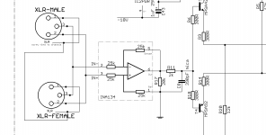
I've reworked the input xlr part and I'm attaching the snapshot of that now.
I thought I should just get rid of the jumpers, since they're really not useful there, and I tied the 4th pins to the pins 1 and I'm going to us the inner lead in the male plug screw hole to get chassis contact. I will have to be careful if the rear plate is anodized or painted, as I want it black, and the connectivity will have to be carefully checked with the screw in place.
So then on the pcb, I can have those chassis traces independent from the main ground plane and keep the signal ground clean.
Any comments on this?
Attachments
what is a "little obsolete" with this design?
any suggestions to improve?
Personally I don't think much could be done to really improve it, as our good professor did a great design job.
The main thing that bothers me with it is his choice of using those diodes to sense the heatsink, which requires more wires, can never be in a really good thermal contact, even as he prescribed to put them through those holes in the heatsink. This is akward and the wiring not easy and tidy. I don't think the thermal tracking is as good that way as a TO126 or TO220 can be on the main sink.
So this is one of the slight changes that I wanted to make, which should have nothing to do with sound quality anyway, just perhaps the thermal stability, which I would think should be better with the transistor on the main heatsink.
One small change I recently made, which really doesn't change anything either about sound, is to make use of beefier flyback diodes. He recommends the 1N400x types, but they could be sometimes pushed a little hard when the protection activates. So I figured using the 1N540x would be better.
I am considering adding input mute, probably right after that balanced line receiver or perhaps closer to the input diffs, on their base resistors, maybe with a J111 or J112 type, used as a shunt and not in series with the sound. This shouldn't alter sound quality or not enough to notice.
imho. "best sound quality possible" is based on personal realities and may not be good for another....
when someone praises a design as "best sound quality possible" and yet sells kits for those, i get scared....
I conquer!
And I've never heard any complaints about the leach amp sound quality. Plus I have yet to see anything that would truly be better.
Like I mentioned before, I'm not seeking that ridiculously low THD, as it's not the harshest on the ears, and that's probably why the leach amp sounds so good, it's a low tim after all and its THD reading may not be as low as some others, but I'm sure it sounds better than some other more "modern" amps with lower THD.
I am satisfied with the leach amp, I don't think of it as obsolete and old design, it's still top of the line.
- Status
- This old topic is closed. If you want to reopen this topic, contact a moderator using the "Report Post" button.
- Home
- Amplifiers
- Solid State
- Work In Progress... Leach Based Amplifier