Hello guys!
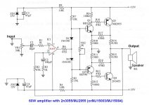
I came across this circuit amplifier, so I wonder if this circuit will work well without oscillations?
What kind of sound quality to give so.
They gave some possible changes to the schematic in order to improve?
What operating amplifier (OPA-IC1), LF351, NE5534N or TL071 here would be most suited to the this amplifier??
Is may include the inclusion of the speaker output impedance of 4R?
Anybody can do a simulation of this circuit.
Thanks for your help and suggestions!
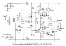
Attachments
Last edited:
Will latch up to the rail until you add a resistor from pin 3 to ground, try 47K.
Need an output Zobel, 10Ω+0.1µF should do.
Choose a better opamp, the old bi-fet's will latch to the negative rail when you drive the amp hard.
There needs to be some small resistors in series with the diodes, there is not enough bias.
Bias pot won't work as drawn, will only reduce it further into class B.
Needs frequency compensation in the feedback loop.
I would add 1nF caps in parallel with R17 and R14.
I would change R18 and R13 to 4.7Ω
May need 47Ω in the base of Q1 and Q2.
Change the collector resistors to 0.22Ω, and add another 0.22Ω pair in the actual emitter circuit.
Last edited:
Changes in the sematic
Guys go on,....
Mr djk, thanks for are suggestions for some changes in the sematic!Will latch up to the rail until you add a resistor from pin 3 to ground, try 47K.
Need an output Zobel, 10Ω+0.1µF should do.
Choose a better opamp, the old bi-fet's will latch to the negative rail when you drive the amp hard.
There needs to be some small resistors in series with the diodes, there is not enough bias.
Bias pot won't work as drawn, will only reduce it further into class B.
Needs frequency compensation in the feedback loop.
I would add 1nF caps in parallel with R17 and R14.
I would change R18 and R13 to 4.7Ω
May need 47Ω in the base of Q1 and Q2.
Change the collector resistors to 0.22Ω, and add another 0.22Ω pair in the actual emitter circuit.
Guys go on,....
Attachments
Last edited:
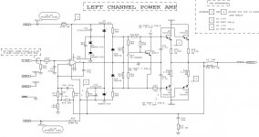
Puccini audio schematic
Give some website of these
Think of this schemtic!?
Thanks
Hi sreten!Hi,
Search on "Puccini", "Brio" and "Texan" amplifiers.
All use standard audio op-amps for the 1st stage.
rgds, sreten.
Give some website of these
Think of this schemtic!?
Thanks
Attachments
Last edited:
Hi sreten!
Give some websiteof these
Thanks
Hi,
You've got a problem using Google ?
rgds, sreten.
Yes for yahoo!?Hi,
You've got a problem using Google ?
rgds, sreten.
Hi,
Search on "Puccini", "Brio" and "Texan" amplifiers.
All use standard audio op-amps for the 1st stage.
rgds, sreten.
The Puccini very old series use operational amplifier like NE5534, the new are fully discrete
- Status
- This old topic is closed. If you want to reopen this topic, contact a moderator using the "Report Post" button.
- Home
- Amplifiers
- Solid State
- 60W simple Audio amplifier with TL071