Folks - i've searched the forum and read a number of posts, but now i'm just confused!
I am restoring a NAD 2100 power amp which I picked up for a great price. I am working through it, replacing and upgrading components where they are off spec due to age. It's a real pleasure saving this from the scrap-heap and also a great opportunity for me to learn more about amplifier circuits. I am hoping an experienced tech help clarify a question on input impedance and the role of the components at the front end?:
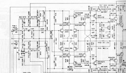
The attached schematic illustrates the question, (only shows the left channel input, to limit the upload size, but I have done identical work on both channels): I upgraded the aging 47uF electrolytic input coupling caps, to 4.7uF PP (C401), to improve the signal path. In order to maintain the correct RC, I also changed R403 from 10k to 100k - is this a good approach? The resulting audio output sounds balanced and far more detailed than before with good musicality, but I do want to maintain the original circuit balance or improve on it if possible.
I'm also confused by the role of the multiple resistors R487, R401, R403, R405 before the differential pairs, and in particular how they impact input impedance and therefore signal - any advice you can give to a keen amateur would be much appreciated") I really should post some photos of the work, but that will follow shortly.
I really should post some photos of the work, but that will follow shortly.
Will
I am restoring a NAD 2100 power amp which I picked up for a great price. I am working through it, replacing and upgrading components where they are off spec due to age. It's a real pleasure saving this from the scrap-heap and also a great opportunity for me to learn more about amplifier circuits. I am hoping an experienced tech help clarify a question on input impedance and the role of the components at the front end?:
The attached schematic illustrates the question, (only shows the left channel input, to limit the upload size, but I have done identical work on both channels): I upgraded the aging 47uF electrolytic input coupling caps, to 4.7uF PP (C401), to improve the signal path. In order to maintain the correct RC, I also changed R403 from 10k to 100k - is this a good approach? The resulting audio output sounds balanced and far more detailed than before with good musicality, but I do want to maintain the original circuit balance or improve on it if possible.
I'm also confused by the role of the multiple resistors R487, R401, R403, R405 before the differential pairs, and in particular how they impact input impedance and therefore signal - any advice you can give to a keen amateur would be much appreciated
I really should post some photos of the work, but that will follow shortly.Will
Attachments
OK...
What you have done is upset the balance of the input stage. You need to check the DC offset (DC voltage across the speakers is below say 50 to 100 mv). Upsetting the balance will increase and alter the distribution of harmonics (harmonic distortion). You might like what you hear.
R487... has minimal effect. Not really sure why its there (can't see where that trace goes off too)
R401 and 403 are in parallel as far as AC goes and set the basic input impedance.
R405 (and technically plus R487) form an RF filter with C403. In fact all the components "interact" a little such as R403 and R405 being "across" that cap.
DC offset is the main thing to check for now.
Thanks for your very quick response Mooly - the left channel shows 89mV and the right is at 4mV DC offset. I would think that the left channel is likely due to poor transistor matching on my part, since i had to replace a couple - i'm waiting for another batch of transistors to select for better gain matching.
Since i made similar mods to both channels, looking at the right channel value, it would suggest that there is no issue.
If i returned R403 to the 10k value, do you know if this would potentially be a more satisfactory solution? (even with the decrease in capacitance value from 47 to 4.7uF?), i.e. back within spec?
I've attached a new schematic showing both channels, just fYI
Thanks Mooly
Will

So... the 100 ohm looks to be to protect the pot from any possible damage if DC were present from the preamp and to protect the contacts of the switches from damage. It seems unlikely but even a 4.7uf cap charged with a couple of volts could degrade a switch contact if it discharged via a closing contact. The 100 ohm stops that.
The DC balance of the input stage relies on the base current being equal (and transistor matching). The 12k (R433) should be matched on the other side by R403 + R405 which comes in at 11.8k. Close enough. Increasing R403 upsets that balance.
The DC balance of the input stage relies on the base current being equal (and transistor matching). The 12k (R433) should be matched on the other side by R403 + R405 which comes in at 11.8k. Close enough. Increasing R403 upsets that balance.
R401 discharges the output cap in the preamp, important on tube preamps.
R403 has to provide the difference in base currents between the PNP and NPN pairs. If they are well matched the absolute value is not that big of a deal.
I used to sell a turn-key subwoofer system with this kind of a front-end on the amplifier. If the DC was a bit high I would just lower the value of this resistor a bit, rather than go to the trouble of fiddling with the transistors.
interesting! Because yesterday I changed R403 back to 10k from 100k and the offset immediately dropped from 89mV down to 7mV with that single change - confirms exactly what you and Mooly have said. I'll get around to the other channel this morning. I've learned to love the channel architecture of this amp (and of course it's clean sound). I need another to work on now so I can bi-amp them in my system Thanks djk. Will
Thanks djk. Will- Status
- This old topic is closed. If you want to reopen this topic, contact a moderator using the "Report Post" button.
- Home
- Amplifiers
- Solid State
- NAD 2100 input impedance/caps question