Hi everyone,
I'm projecting a lateral MOSFET amplifier using BUZ900/905 pair, but my intention is to make an amplifier that can deliver 200 Wrms to a 4 ohm load and 100 Wrms to 8 ohm, with 30 dB of gain, and with THD20 < 0.005% and THD1 < 0.0005% (if possible in the ppm region 0.00000x). I'm trying to optimize this circuit for almost one year [a circuit similar to the Bob Cordell's designs and more recently with some improvements of the Honey Badger by Peter V (ostripper)], the problem is that I can get THD20 characteristics lower than 0.02% and THD1 values lower than 0.0000x%, even using advanced compensation methods like TMC. I'm wondering if I should give up from this project, and start a new one from scratch, but with a condition, the output pair will have the BUZ900/905 pair of MOSFETs. I'm thinking maybe in a CFA design, maybe something similar to the circuit design by dadod, but I don't know nothing about CFA
There are any documentation about out to develop and test a CFA audio amplifier?
Does anyone with more MOSFET experience give me an idea to what I should do?
I don't know if I should change this design to meet this requirements (if possible), or if I should redraw the circuit from scratch, maybe using another topology.
Best regards,
Daniel
Attachments
Compare your input/vas stage with
http://www.diyaudio.com/forums/soli...b-power-amp-200w8r-400w4r-14.html#post3577892
Or try my asc files and replace the bias stage and bjt ops with your ops. During design phase remove input caps and NFB capacitors.
BR, Toni
http://www.diyaudio.com/forums/soli...b-power-amp-200w8r-400w4r-14.html#post3577892
Or try my asc files and replace the bias stage and bjt ops with your ops. During design phase remove input caps and NFB capacitors.
BR, Toni
If you want low THD you need high open loop gain and use some sort of two pole compensation to get good THD20. The high open loop gain will give large amounts of feedback correction and hence low THD. Amount of feedback correction available = open loop gain - closed loop gain.
Hi everyone, Thank you for helping me,
The solution that you've presented seems very interesting mcd99uk, increasing open loop gain to have more bandwidth, and using TPC to increase the slew rate at higher frequencies. For increasing the open loop gain I have to lower the degeneration resistors at the IPS and VAS, what do you think that can be a good degeneration factor? As about the compensation method I understand better TMC, but maybe TPC has better distortion characteristics, the main reason that leads me to choose TMC is the absence of square wave overshoot.
PS: Increasing open loop gain leads to higher cmiller values, right?
Best regards,
Daniel
Last edited:
Hi Daniel,
For an ultra low distortion amp (with laterals) see:
Home
PGP Amplifier
PGP (mirror plus more info)
Cheers, E.
Hi Edmond,
How good measured distortion corresponded to the simulated one, as there are no good lateral mosfet models?
BR Damir
Good question Damir.
I just estimated the distortion by filtering out the artifacts (i.e. higher harmonics) caused by the imperfections of the lateral models.
edit: The filtered THD sims were reasonable in line with the real THD figugers, though a little optimistic.
Cheers, E.
I just estimated the distortion by filtering out the artifacts (i.e. higher harmonics) caused by the imperfections of the lateral models.
edit: The filtered THD sims were reasonable in line with the real THD figugers, though a little optimistic.
Cheers, E.
Last edited:
Good question Damir.
I just estimated the distortion by filtering out the artifacts (i.e. higher harmonics) caused by the imperfections of the lateral models.
edit: The filtered THD sims were reasonable in line with the real THD figugers, though a little optimistic.
Cheers, E.
What models did you use?
BR Damir
Just mainstream stuff. Sorry, I can't remember where I got from (it's a long time ago). Anyhow, these models were way too simplistic and didn't account for the sub-threshold trans-conduction.What models did you use?
BR Damir
Cheers, E.
Hi everyone,
I've modified the astx's circuit present in the thread entitled "2stageEF high performance class AB power amp / 200W8R / 400W4R", and now I've lower THD20 characteristics [0.007% with 4 ohm (at maximum power), 0.006% with 8 ohm (at maximum power)], and those results are fine to me, but THD1 characteristics are a little high [0.0007% with 4 ohm (at maximum power), 0.0007% with 8 ohm (at maximum power)]. I've to thank to astx, that's a fine amp
What's the secret of this amp? It's the double EF? This circuit it's similar to my circuit. How I can get lower THD1 with this design, with my design I've higher THD20 characteristics (maximum 0.01%), but lower THD1 characteristics (maximum 0.00008 %). I can have an amp that can combine the THD1 characteristics from my amp with the good THD20 characteristics of the double EF amplifier by astx, is that possible?
Best regards,
Daniel
Attachments
Hi everyone,
I think that I finally hit it my objective, I've to thank you all, especially to astx and ostripper (Peter V), this amp is capable of perform 200W/4 ohm with THD20 of less than 0.005 % and 100W/8 ohm with THD20 of less than 0.004 %
THD1 remains bellow 0.0001 %, (4 Wrms into 8 ohm with 0.000004 % THD1 xD).
To achieve this I've removed the zobel networks (because they cause a huge phase lag) from the MOSFETs and EF, and than with more phase to spare, I can use lower TMC values to increase slew rate
The reverse of this improvement is less OPS stability, due to the absence of zobel networks, but I don't see another option, zobels kill the amps phase margin
Now the amp has 68 degrees PM, acceptable, right?
I'm a little concerned about OPS local stability while driving inductive and capacitive loads
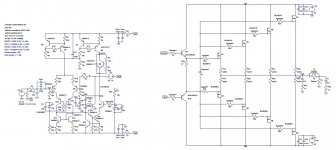
Circuit diagram attached + models
Best regards,
Daniel
I think that I finally hit it my objective, I've to thank you all, especially to astx and ostripper (Peter V), this amp is capable of perform 200W/4 ohm with THD20 of less than 0.005 % and 100W/8 ohm with THD20 of less than 0.004 %
THD1 remains bellow 0.0001 %, (4 Wrms into 8 ohm with 0.000004 % THD1 xD).
To achieve this I've removed the zobel networks (because they cause a huge phase lag) from the MOSFETs and EF, and than with more phase to spare, I can use lower TMC values to increase slew rate
The reverse of this improvement is less OPS stability, due to the absence of zobel networks, but I don't see another option, zobels kill the amps phase margin
Now the amp has 68 degrees PM, acceptable, right?
I'm a little concerned about OPS local stability while driving inductive and capacitive loads
Circuit diagram attached + models
Best regards,
Daniel
Attachments
Last edited:
Dear Daniel,
you may try some of these steps:
Run SOA tests to be sure your output drivers and power fets will survive.
And then it would be time to build a prototype to verify that your BUZ901/ BUZ906 do what you want.
Good luck, Toni
you may try some of these steps:
- try to use BC550C or BC337-40 for Q13/Q14/Q5
- try to use BC560C or BC327-40 for Q4/Q7
- try to use KSC1845 for Q11
- split R6 into R6a and R6b and check when Q12 begins to limit current on maximum load or overload - it should not start current limiting of Q5 even if you are at or near clipping.
- add 47 - 100R to Q17 base
- add 47 - 100R to bases of Q15/Q16 and add a capacitor 22µ parallel to D5
- replace D1-D4 by a green LED and add a parallel capacitor 22µ
Run SOA tests to be sure your output drivers and power fets will survive.
And then it would be time to build a prototype to verify that your BUZ901/ BUZ906 do what you want.
Good luck, Toni
Dear Daniel,
forgot to say: don't skip zobel and output coils. This helps to keep your amplifier and speaker running and avoids high frequency oscillation on complex load or EMI from outside. E.g. use split zobels:
amplifier output - 47nF/10R - 1µH coil ||10R - 47nF/10R - speaker output
I have done many measurements and hearing test - this filter doesn't kill your good THD values.
Br, Toni
Hi everyone,
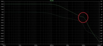
I've made some changes as astx suggested, the ones that I've seen that slightly lower THD, and I've added the capacitors. Now I'm concerned about a gain peaking appearing at the MHz region, I don't know if that's normal or it's some form of instability that should be avoided (vout bode plots with v1 influence and vin influence attached). After solving this problem, if it's necessary, I'm thinking in incorporating a simple output protection circuit, maybe similar to the one that astx used, how the values are calculated?
Do you think that I should use a Hawksford error correction circuit like bear suggested?
I don't know almost anything about error correction.
It seems that the problem that causes this peaking is in the IPS or VAS (TCS or TIS) because the amp7_tmc.asc circuit has a similar IPS-VAS topology and BJT output and the same happens. With NPN (IPS) and PNP (VAS) there's almost no peaking, like in circuit amp7_tmc_hb6.asc
PS (about amp7_tmc_hb5.asc): The amplifier has good square wave response, without overshoot.
The circuit's phase margin is 68 degrees.
Best regards,
Daniel
Attachments
Last edited:
Hi everyone,
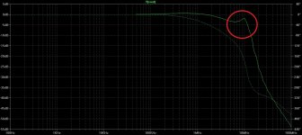
That's right the KSC3503/KSA1381 pair does a good a job at the VAS, a small reduction in THD1, I still with 68º phase margin and 11 dB gain margin, there's no peakings on open and closed loop bode plots and now I can use 330 ohm for the N MOSFET gates and 220 ohm for the P MOSFET gates as suggested by Semelab to prevent local parasitic oscillations
I'm still interested on astx's simple VI limiter circuit, what I have to do to adapt it?
PS: I don't have the KSC1845 models for LTSpice, can you give them to me please?
The split resistors for Q15/Q16 are a good or a bad idea?
And as about adding the Hawksford error correction circuit, it's a good or bad idea?
Best regards,
Daniel
Attachments
Last edited:
read the SOA parts in "2stageEF ..." thread. Build your own SOA curve for your BUZ90X's, e.g.: use step feature of LTSpice using low ohmic output load at full power to find the correct resistor values....
I'm still interested on astx's simple VI limiter circuit, what I have to do to adapt it?
...
Maybe you want to experiment with single or dual slope VI limiter - ask Michael Kiwanuka (PM him @ michaelkiwanuka) for his excellent SOA paper.
...
PS: I don't have the KSC1845 models for LTSpice, can you give them to me please?
...
download "my_libs.lib" from my "2stageEF ..." thread
EF's are prone to oscillation so I try to use them whenever possible....
The split resistors for Q15/Q16 are a good or a bad idea?
...
BR, Toni
- Status
- This old topic is closed. If you want to reopen this topic, contact a moderator using the "Report Post" button.
- Home
- Amplifiers
- Solid State
- How to make a low distortion lateral MOSFET amplifier?