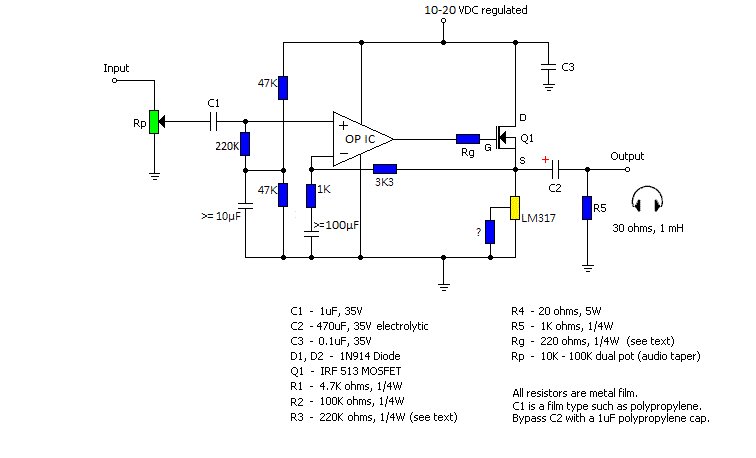
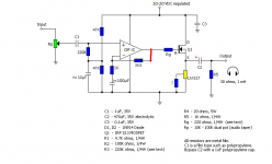
This is my modification from a MOSFET headamp schematic:
I put an OP-amp and biased the non-inverting input.
Is this schematic correct? Or any suggestions?
I put an OP-amp and biased the non-inverting input.
Is this schematic correct? Or any suggestions?
Suggestions...
R2 and R3 are not needed. The opamp sets the DC conditions on the FET.
R4 could be replaced with a constant current sink.
The junction of the three 220k resistors should be decoupled to ground. You could also replace the divider network with a fixed voltage reference using a zener etc.
D1 and D2 servo no purpose. The opamp output will always be between 0v and supply.
Most important of all, the 10k feedback return must be AC coupled with this being a single rail design.
R1 is not needed.
Thanks for the suggestions, Mooly.
"The junction of the three 220k resistors should be decoupled to ground" this mean I should add a cap between the junction and ground, but in what value?
And what "the 10k feedback return must be AC coupled" means?
"The junction of the three 220k resistors should be decoupled to ground" this mean I should add a cap between the junction and ground, but in what value?
And what "the 10k feedback return must be AC coupled" means?
1-10µ electrolytic should do fine.Thanks for the suggestions, Mooly.
"The junction of the three 220k resistors should be decoupled to ground" this mean I should add a cap between the junction and ground, but in what value?
Let's quickly do the math and find out why the circuit wouldn't work too well like that.And what "the 10k feedback return must be AC coupled" means?
Opamp 101 says V(+in) = V(-in).
Now DC wise,
V(+in) = +Vs/2 (ignoring the -220k * Ib term for now)
V(-in) = V(Q1 source) * 10k/43k
From which it follows that
V(Q1 source) ~= +Vs/2 * 43k/10k ~= 2 * +Vs > +Vs (!!!) 😱
IOW, the circuit would probably just latch up and do nothing useful.
Once you insert a capacitor in series with the 10k (>=10µ or so), we get
V(-in) = V(Q1 source)
which yields the more useful
V(Q1 source) = +Vs/2
Expect to be tweaking the 220k/220k input divider values for maximum output voltage swing, as you are losing a few volts (maybe 4 V) in the MOSFET G-S. (They wouldn't need to be that high anyway, 47k+47k with a 4µ7-10µ cap would do fine.)
A sufficiently low-noise opamp would warrant reducing the feedback network resistors to 3k3/1k, with a >=100µ cap.
Replacing R4 by at least a LM317 current source (well, sink) is highly recommended, as it vastly improves open-loop performance at marginally increased component count (1 LM317 w/ cooling, 1 resistor).
Thanks for the suggestions, Mooly.
"The junction of the three 220k resistors should be decoupled to ground" this mean I should add a cap between the junction and ground, but in what value?
And what "the 10k feedback return must be AC coupled" means?
sgrossklass saved me explaining it 😀 And if you are not sure then ask 🙂
Interesting idea. On some op-amps this is an advantage and on others an disadvantage - so I think. Are there any experiences in this matter ?If you take the opamp feedback not from the output, you'll get much more interesting sounding amplifier🙂
- Status
- Not open for further replies.
- Home
- Amplifiers
- Solid State
- OP-amp + Class A MOSFET follower