Hi OS,
Could instead of connecting R25 and R26 to ground, two other resistors be placed between VAS base and collector (local feedback) or two resistors from VAS out to the LTP inverting input?
Why have choosen for this VAS loading?
Cheers
VAS loading -
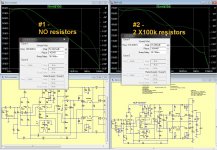
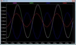
Look at the comparison below:
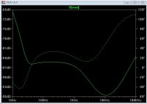
Amp #1 - has no loading. LF gain is 78db. it's bandwidth (UG-unity gain) is 390Khz , and the lead
compensation (C6) had to be increased to 15pF to keep -103 degrees margin.
Less than 1db extra gain at 20K available for feedback. This combined with
the extra distortion of a larger C6 adds up to .01% THD20.
Amp #2 - Loaded by the 2- 100K resistors .LF gain is only 66db, the margin goes out to 618K
the gain at 20k is 32db! 32- the 26 of the amp leaves 6db extra.
Besides at much better .002% THD20 , C6 can be reduced to 10p to give the same -103 degree margin.
H3 also decreases with the loading.
Conclusion - loading sacrifices gain at lower frequencies for more gain at
the higher ones. 1/5th the THD at 20K is the result. TMC does the same
work in a typical "blameless" topology.
This is also why you see the THD plots of most amps " reach skyward"
at 25 to 30k - no extra gain above 20K !
 PS-this is why Sansui used the loading resistor.
OS
Attachments
This I understand OS.
Before I had read Cordell's book, loading the VAS with R's to ground is what I did also. "This is no the way a VAS stage should be treathed" according to Bob Cordell.
My current amp in progress is using high value R's between VAS output and base. It seems to me that this solution is minimum as good as VAS loading to ground.
Have you experience whit this?
Regards
This I understand OS.
Before I had read Cordell's book, loading the VAS with R's to ground is what I did also. "This is no the way a VAS stage should be treathed" according to Bob Cordell.
My current amp in progress is using high value R's between VAS output and base. It seems to me that this solution is minimum as good as VAS loading to ground.
Have you experience whit this?
Regards
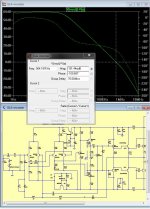
You mean C-B on the VAS devices. If that is what you mean....
(below) ONLY 54db LF gain (100k - 60db+ w/ 330k) , UG rises to 550+khz , Margin remains the same.
FFT remains the same (as with no loading). ?
Tried 330k as well ....
This seems to lower gain globally , instead of "shifting" it from LF to HF.
" no way to treat a VAS" ... ha ha ! It is treated far worse from the standard EF2 (load + capacitance).
OS
Attachments
Last edited:
Wow, very nice map OS! The "Frankenstein" version is going to be my next project.
By the way, the name 'Survivor" reminds me of the 80s band that did the theme song "Eye of the Tiger" for Rocky III, a fitting name for a simple, rugged & quality amp.
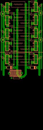
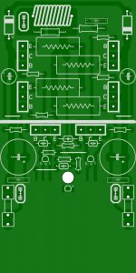
Combined the 2 PCB's into one. Just print 1/2 the board for 70W , all of it for
"frankenstien" (400W).
76mm X 228mm , option to use TO-220 or TO-3p drivers (both pads).
You can mount the TO-3P on the main heatsink or use "bare" TO-220's above board (a little pcb heatsink ?)
Vbe will be a little TO-92 device face down under the board.
Break the board off (or don not print/transfer it) at the GLA70/GLA400 line
you have the original 70W Z5900 sansui.
OS
Attachments
For reliability purpose it would be safe to put 1.5k-2.2k resistors in serial
with the regulating transistors wich should be BD139/140 or whatever cheap
TO126 complementary pair as the BC would have to endure too much
power for their rating , several hundreds mWs in that case.
Other than that i did a few sims to check the design and set apart
that the lead comp is mandatory the overall perfs are excellent ,
i ll post a few graphs once i have a better picture.
I'm listening - I like...
The amp this project is reverse engineered from is indeed musical. The badger
has a little more bass ... but the GLA can have a bigger input cap.
As far as the circuit , a few improvements while preserving the "vintage" aspects.
#1 - level shifter has a added cascode (Q8)..can use KSA1845 safely here now.
#2 - C22 output "suckout" cap. The tiny switching distortion "pulse" is gone
from the stages.
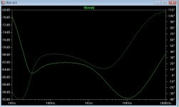
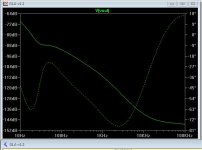
#3 - C9 and C12 at 100uF. This brings PSRR (photo 1) to -82db , and even below
-90db at the high end (10Khz).
#4 - Reverse diode protection for the zener regulators (D2/3).
#5 - balanced the currents for Q1-4 , all are at 1.4mA (photo 2).
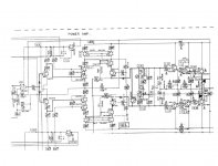
The final V1.2 schema (photo 3). .003% full power 20Khz at 2R !
OS
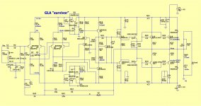
The amp this project is reverse engineered from is indeed musical. The badger
has a little more bass ... but the GLA can have a bigger input cap.
As far as the circuit , a few improvements while preserving the "vintage" aspects.
#1 - level shifter has a added cascode (Q8)..can use KSA1845 safely here now.
#2 - C22 output "suckout" cap. The tiny switching distortion "pulse" is gone
from the stages.
#3 - C9 and C12 at 100uF. This brings PSRR (photo 1) to -82db , and even below
-90db at the high end (10Khz).
#4 - Reverse diode protection for the zener regulators (D2/3).
#5 - balanced the currents for Q1-4 , all are at 1.4mA (photo 2).
The final V1.2 schema (photo 3). .003% full power 20Khz at 2R !
OS
Attachments
Last edited:
I like the look of this little project ostripper, I will be keeping an eye on this one. Thanks for your efforts.
A little variety is good !
Most have used the "blameless" , that design is overused.
Then there are the CFA amps (current feedback) , this amp CAN do
150+ V/uS slew ... and it is a VFA (voltage feedback) amp.
The boards will be done (below). This is a 200W/4R with only 2 pair 21193/4
50V rails .... perfect Sub amp
.The outputs will be driven by NJW0302/0281 (smaller outputs !
).This is the most stable triple OPS I've simulated ... PLUS , I have the real amp
for reference. I can't lose.
OS
Attachments
Last edited:
If I was to use a 28+28vac (56vct) transformer and a single set of MJL21193/4 outputs, what resistor values may be changed/optimized for the 40+40vdc rails?
Different amp topology , Dan.
This one can scale from 30V to 100V rails because
of the independent regulated differentials and level shifter. At 80V and above
you might have to use 47-68K to feed the Zener's like in the badger cascode.
Sansui uses the same circuit for the Z- 3900 (40V) , 4900 (50V) , 5900 (65V).
You can also add AS MANY outputs as you like. Unlike the S. American amps
,The triple OPS + the NJW0281/0302 could easily do a 20 device output stage.
Designing a 800 watt /2R capable sub amp is as easy as buying more transistors.
My two reasons for this endeavor is the great sound/ultra low S/N of this amp
and the fact it "survived" 32 years of college use only needing a re-cap.
One EXCELLENT circuit !
One more slight change - use a KSC3503/BD139 for the positive zener regulator,
at 6mA , wahab was correct to use a more robust device here. The small
KSA992 can stay for the negative reg. (only 2.8ma).
OS
6ma, bd139? Okay to use 2n5551?
The recomendation of a TO126 was for 50V rails but even with 40V
it would be cautious to use this package for reliability purposes.
Voltage drop around the positive regulation being 25V ,
6ma x 25V = 150mW.
2N5551 junction/ambiant thermal resistance is 200°C/W ,
hence the junction will be 200 x 0.15 = 30°C over ambiant ,
a BD 139 is 100°C/W , differential temp would be just 15°C.
Power circuit hack question.
Meanwhile, the power circuit. . .
See the crazy diodes?
Is it applicable (with 6a1, 10a1)? Or is it best reserved for small amplifiers?
Would take only minutes to test this, except that you'll need at least 220u//220u per each rail at the amp board because that trick won't show off with just 220u.
Anyway, that VDM diode trick doesn't cost much and it could be fun! For Dual Mono with only one transformer, this way to "individualize" the amplifier boards with diodes is cheaper than regulators.
What do you think?
Practically, play Zac Brown's "Jump Right In" long enough to get past the opening drum hit. . . add the 220u caps (to get your 440u), add the 6a1's (or the 6a05's from the radio shack--that 4 pack is just right--2 per amp board) located onto the amp boards, series to the power cables, and play the song again.
That should make the difference between just a bump or rolling thunder. So, does it work on discrete amplifiers? May be really fun if it does!
I have a weird affinity for the LM1875, but rather this way (Schematic for LM1875 Turbo II). The clipping pattern is tame and the dynamics blockbuster. It does use an offboard dc supply. See what I did to the amp board power circuit there? As far as I know, that schematic is unique, it blocks some of the crosstalk of a stereo pair and it promotes more interesting dynamics (vibrates the whole house).The amp also exhibits the best clipping behavior
Meanwhile, the power circuit. . .
See the crazy diodes?
Is it applicable (with 6a1, 10a1)? Or is it best reserved for small amplifiers?
Would take only minutes to test this, except that you'll need at least 220u//220u per each rail at the amp board because that trick won't show off with just 220u.
Anyway, that VDM diode trick doesn't cost much and it could be fun! For Dual Mono with only one transformer, this way to "individualize" the amplifier boards with diodes is cheaper than regulators.
What do you think?
Practically, play Zac Brown's "Jump Right In" long enough to get past the opening drum hit. . . add the 220u caps (to get your 440u), add the 6a1's (or the 6a05's from the radio shack--that 4 pack is just right--2 per amp board) located onto the amp boards, series to the power cables, and play the song again.
That should make the difference between just a bump or rolling thunder. So, does it work on discrete amplifiers? May be really fun if it does!
Last edited:
Dan , if you use 2 bridges with 2 separate capacitor banks you essentially have
each amp "isolated" by diode (like your schema).
Both on my two Badger's and when I do two of these amps , I will use 25A
bridges for EACH channel and 4 X 8200uf caps for each.
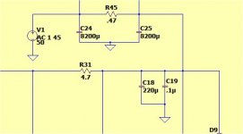
The GLA already has very good psrr (below 1). I wondered how it could even
play music at low volumes with total capacitor failure !
Add a simple CRC (8200uf -.47R/10W-8200uf - below 2) , and this amp is
effectively a dual mono (spec wise - BELOW 3 !)
2- 10W/1R for R in parallel would most likely handle a 100-200W amp.
OS
each amp "isolated" by diode (like your schema).
Both on my two Badger's and when I do two of these amps , I will use 25A
bridges for EACH channel and 4 X 8200uf caps for each.
The GLA already has very good psrr (below 1). I wondered how it could even
play music at low volumes with total capacitor failure !
Add a simple CRC (8200uf -.47R/10W-8200uf - below 2) , and this amp is
effectively a dual mono (spec wise - BELOW 3 !)
2- 10W/1R for R in parallel would most likely handle a 100-200W amp.
OS
Attachments
Nice amp, this is my favorite old amp Pioneer A70.
All new Marantz amps are clone of old Pioneer amps, symetrical CFA are clone of Pioneer A400.
Regards
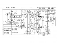
The A-70 is indeed interesting ... is it "stepped" (dynamic power supply) ?
The VAS is different , too ! Must simulate it ...
OS
The A-70 is indeed interesting ... is it "stepped" (dynamic power supply) ?
The VAS is different , too ! Must simulate it ...
OS
It's 'stepped' and there is 'non switcing' circuit
Hi Ostripper
greetings i am interested in buildilng this GLA amp scalable to 800 watts using
10 output pairs at 70 volts dc rails i cant find KSA 992 TRS so can i use 2sa970 as i have these trs just need your confirmation and guidance to make this amp before i start designing this pcb
warm regards
andrew lebon
greetings i am interested in buildilng this GLA amp scalable to 800 watts using
10 output pairs at 70 volts dc rails i cant find KSA 992 TRS so can i use 2sa970 as i have these trs just need your confirmation and guidance to make this amp before i start designing this pcb
warm regards
andrew lebon
Hi Ostripper
greetings i am interested in buildilng this GLA amp scalable to 800 watts using
10 output pairs at 70 volts dc rails i cant find KSA 992 TRS so can i use 2sa970 as i have these trs just need your confirmation and guidance to make this amp before i start designing this pcb
warm regards
andrew lebon
2SA970 would be a good substitute. This device is used in many a vintage amp
such as this.
Q1-4 on this amp form a extreme high gain quad differential , best to keep the
Hfe 200-300 (970 grade- ? - "GR"). I have only simulated a Zetex high gain pair for
Q1-4 (1200Hfe) - no issue.
The Q5 and 6 regulators should be high voltage to-126 devices , R15-16 should be
47K for 70V rails. ABSOLUTELY use output devices for the drivers and
even a more robust device for predrivers (mje340/350 or 2sa1381/sc3503).
.asc (below) for 70V rails - all is good !!
EDIT - Bob Cordell once advised to keep the drivers as the highest Ft devices for the ultimate
stability in a triple. mje340/350 - Ft 10mhz , NJW0281/0302 - Ft 30mhz , and a "slow" output pair MJL21193/4 - 4 mhz ....
OS
Attachments
Last edited:
- Home
- Amplifiers
- Solid State
- GLA (good little amp) "survivor"