Of course it does - one must decide what is more important.
OTOH my real life measurements THD+N 20k@200W@8R (bw 80k) - 0.0016% are made including this diode - so what are we talking about...
I like your work and your ideas, but technically I can't agree with you on that, it is the worst place to control the clipping (VAS). Reversed biased diode acts as a varicap diode with very non linear capacitance change. If you do all to get low distortion then adding that diode increases distortion not just few ppm, but a lot. In my simulation I used MMSD4148 diode with very low Cjo = 0.64pF (sorry I don't have BAV21 model) and THD20k increased from 1.57 ppm to 9.74 ppm at output level close to clipping.
This is 6.2 times or 15.8 dB. Of course if an amp is with higher distortion then the diode distortion could be masked.
By the way, adding a zener as suggested did improved distortion and clipping behavior, but just a little, so one can decide to use it or not, the protection resistor is a major player here.
cheers Damir
Attachments
Have had the same idea but has not worked for me. The clipping behavior at 20kHz was "bad" again and the distortions were higher.Would a series pair of diodes still work in reducing the glitch as clipping is approached and passed?
The series pair would automatically halve the capacitance.
I like your work and your ideas, but technically I can't agree with you on that, it is the worst place to control the clipping (VAS). Reversed biased diode acts as a varicap diode with very non linear capacitance change. If you do all to get low distortion then adding that diode increases distortion not just few ppm, but a lot. In my simulation I used MMSD4148 diode with very low Cjo = 0.64pF (sorry I don't have BAV21 model) and THD20k increased from 1.57 ppm to 9.74 ppm at output level close to clipping.
This is 6.2 times or 15.8 dB. Of course if an amp is with higher distortion then the diode distortion could be masked.
By the way, adding a zener as suggested did improved distortion and clipping behavior, but just a little, so one can decide to use it or not, the protection resistor is a major player here.
cheers Damir
You are right - I always have said "one can decide". The zener variant is a very good compromise as you can now use low Vce devices to get better distortion and clipping behavior.
Even in my simulations it worsens the distortions from 4ppm (20k@200W@8R) to 15ppm near full power. At 20k@50W@8R the simulated distortions are 4.6ppm versus 5.7ppm with diode. During real life measurements I have tested with and without diode - the distortion level was always the same - maybe due to limits of my measurement devices or due to bad diode simulation models.
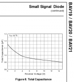
Attached a screenshot of BAV21 capacity versus reverse voltage.
1.15pF (0V) to 0.9pF (14V)
As we can see the worst (and nonlinearest) change rate of capacitance are the first 4 V - these affect the distortions mostly the last 4V be4 clipping of the positive halfwave. During small signal listening the diode is reversed biased about 1/2 of total supply voltage with negligible capacitance changes.
BTW: BAV21 model is from Phillips/NXP:
see NXP website: http://www.nxp.com/documents/spice_model/BAV21.prm
.MODEL BAV21 D
+ IS=21.910E-9
+ N=2.2330
+ RS=1.0000E-3
+ IKF=19.230E-3
+ CJO=1.0300E-12
+ M=.1001
+ VJ=.75
+ ISR=10.010E-21
+ BV=293.10
+ IBV=1.2930E-3
+ TT=51.940E-9
Hope this helps for a decision.
")
BR, Toni
Attachments
Probably too much voltage across the series pair to suppress the saturation effect.

You are right - I always have said "one can decide". The zener variant is a very good compromise as you can now use low Vce devices to get better distortion and clipping behavior.
Even in my simulations it worsens the distortions from 4ppm (20k@200W@8R) to 15ppm near full power. At 20k@50W@8R the simulated distortions are 4.6ppm versus 5.7ppm with diode. During real life measurements I have tested with and without diode - the distortion level was always the same - maybe due to limits of my measurement devices or due to bad diode simulation models.
Attached a screenshot of BAV21 capacity versus reverse voltage.
1.15pF (0V) to 0.9pF (14V)
As we can see the worst (and nonlinearest) change rate of capacitance are the first 4 V - these affect the distortions mostly the last 4V be4 clipping of the positive halfwave. During small signal listening the diode is reversed biased about 1/2 of total supply voltage with negligible capacitance changes.
BTW: BAV21 model is from Phillips/NXP:
see NXP website: http://www.nxp.com/documents/spice_model/BAV21.prm
.MODEL BAV21 D
+ IS=21.910E-9
+ N=2.2330
+ RS=1.0000E-3
+ IKF=19.230E-3
+ CJO=1.0300E-12
+ M=.1001
+ VJ=.75
+ ISR=10.010E-21
+ BV=293.10
+ IBV=1.2930E-3
+ TT=51.940E-9
Hope this helps for a decision.
BR, Toni
I simulated with BAV21 and got almost the same result, a bit lower, 9.18 ppm, thanks for the model.
I think If you really need to better clipping behavior the is better to use Backer clamp.
BR Damir
dadod
Try to solve clipping behavior just in differential input stage, with antiparalell 1N4148 diodes between colectors of curent mirror transistors (some resistor for voltage shift in series with colector Q6 will be needed, without input signal should be across diodes zero voltage).
Or simply connect 3 diodes (1N4148) in series to Q15 base (first cathode) and +Ub of VAS -upper side R18 (last anode), remove Q20 and slightly increase R29 .
dadod
Try to solve clipping behavior just in differential input stage, with antiparalell 1N4148 diodes between colectors of curent mirror transistors (some resistor for voltage shift in series with colector Q6 will be needed, without input signal should be across diodes zero voltage).
Or simply connect 3 diodes (1N4148) in series to Q15 base (first cathode) and +Ub of VAS -upper side R18 (last anode), remove Q20 and slightly increase R29 .
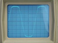
Thank you BV for your suggestion. I tried both and here is the result.
Antiparallel diodes between CM transistor collector did not improve clipping.
Diodes string between EF VAS transistor base and +Ub did help with the clipping behavior if EF protection resistor was set to low value (1k), and did not improve it when that resistor was high enough (10k to 15k) but doubled distortion.
Damir
Baker clamp hasn't helped to cure the 20k clipping as we have a amplifier with NFB. IMHO if you add the baker clamp the VAS still gets into saturation as the NFB wants to correct the heavy distorted output signal. Diode clamp between input LTP hasn't helped either - only increased distortion....
I think If you really need to better clipping behavior the is better to use Backer clamp.
BR Damir
Maybe you get here better results with your CFA using a baker clamp.
BR, Toni
Baker clamp hasn't helped to cure the 20k clipping as we have a amplifier with NFB. IMHO if you add the baker clamp the VAS still gets into saturation as the NFB wants to correct the heavy distorted output signal. Diode clamp between input LTP hasn't helped either - only increased distortion.
Maybe you get here better results with your CFA using a baker clamp.
BR, Toni
I don't get why Baker clamp can't cure the 20k clipping, but if you want to prevent an amp to go in to clipping at all, you have to prevent the input signal to rich that level and use something as Cordell's Clever Klipper, or NAD soft clipping with a diodes.
I don't need Baker clamp with my CFA, look some post back where I started this issue.
BR Damir
This circuit I am using in every my amps for many years...
Could you explain its function, and influence on distortion?
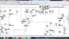
...tip from wojtek5001. This [zener] replaced the VAS protection resistor...
Did some more simulations with this.
Distortion reduced... but only because the Return Ratio increased, so I lost a little PM and stability.
The zener altered the trade-off but I think there was no overall improvement. I will check more.
I was so satisfied when I saw the distortion drop that I almost didn't check for the side effects. Another lesson.
Best wishes
David
2 dadod
Can you post asc file for schematic you are trying to improve clipping behavior? It is much more simple to do something, like talk about it.
Hi BV,
here it is, you can play with it.
Damir
Attachments
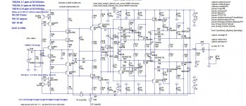
I did some more simulation and came to this a bit simpler schematic. No need for individual OPS mosfet compensation, distortion is still very low, clipping is good, SR is 700 V/usec with no input filter and 200 V/usec with input filter.
Damir
Damir
Attachments
-
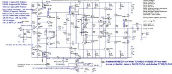 GainWire-TIS-simple-TPC-OIC-LMOSnocomp-200W-2-DCservo-15V-betterCCS.jpg169.5 KB · Views: 418
 -
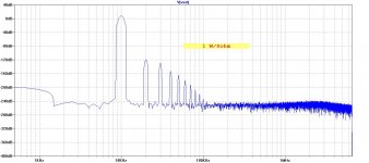 GainWire-TIS-simple-TPC-OIC-LMOSnocomp-200W-2-DCservo-15V-betterCCS-FFT1k-1W_8.jpg130.9 KB · Views: 390
 -
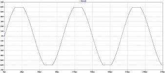 GainWire-TIS-simple-TPC-OIC-LMOSnocomp-200W-2-DCservo-15V-betterCCS-clipping.jpg100.4 KB · Views: 362
- Home
- Amplifiers
- Solid State
- 200W MOSFET CFA amp