Very nice dadod!
Thank you Bonsai, you are to kind.
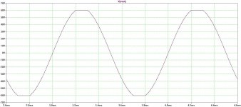
Here is the clipping and FFT at 1kHz and 1W output.
BR Damir
Attachments
Thank you Bonsai, you are to kind.
Here is the clipping and FFT at 1kHz and 1W output.
BR Damir
")
Getting there.
Thx-RNMarsh
which?PSRR!
Or are +ve and -ve the same?
Is "good" at the top of the plot?
which?
Or are +ve and -ve the same?
Is "good" at the top of the plot?
PSRR of +ve, and -ve is even better.
Attachments
The ear, as we all know, is most sensitive in the freq range of approx 3-5KHz. So for listening, that is the range you need max PSRR as a minimum range. [ignoring hum/ps ripple/ cm noise issues]. #144 would be OK at 100dB or more. What comes into play that reduces the PSRR below 1Khz? Would a simple, well placed R increase it at lower freqs?
Thx-RNMarsh
Thx-RNMarsh
Last edited:
The ear, as we all know, is most sensitive in the freq range of approx 3-5KHz. So for listening, that is the range you need max PSRR as a minimum range. [ignoring hum/ps ripple/ cm noise issues]. #144 would be OK at 100dB or more. What comes into play that reduces the PSRR below 1Khz? Would a simple, well placed R increase it at lower freqs?
Thx-RNMarsh
This is if I replace 10 ohm resistors in power filter for the front end with simple cap multipliers.
BR Damir
Attachments

This is if I replace 10 ohm resistors in power filter for the front end with simple cap multipliers.
BR Damir
Finding Cap Multipliers that will handle a voltage above 50 volts is the problem. I have not seen one on the forum. Has anyone else seen one? Keantoken said he was going to do one, but I have yet to see it.
This is if I replace 10 ohm resistors in power filter for the front end with simple cap multipliers.
BR Damir
What is the equiv C needed to get this PSRR down to 100Hz (-100dB) in your circuit? Might not need C-multi. if not too ridiculous value.
-RM
What is the equiv C needed to get this PSRR down to 100Hz (-100dB) in your circuit? Might not need C-multi. if not too ridiculous value.
-RM
Resistor of 33 ohm and capacitor of 1000 uF will do -100 dB at 100 Hz, but it's not easy to find 100 V elco.
BR Damir
Thank you Bonsai, you are to kind.
Here is the clipping and FFT at 1kHz and 1W output.
BR Damir
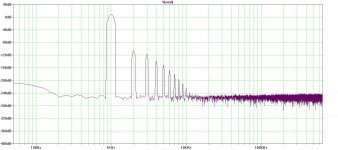
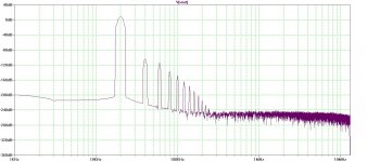
Would you mind to upload fft 20 kHz please?
Would you mind to upload fft 20 kHz please?
Same condition as at 1 kHz.
Attachments
Same condition as at 1 kHz.
Looks nice, this one should not have problems with heights. It has uniformly distributed character over audio band, so should be easily complemented with cables once it comes to play. I think you have serious toy now.
Looks nice, this one should not have problems with heights. It has uniformly distributed character over audio band, so should be easily complemented with cables once it comes to play. I think you have serious toy now.
Thanks!
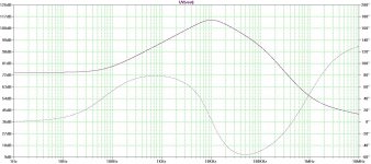
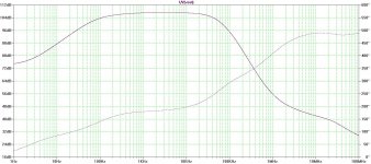
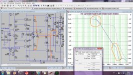
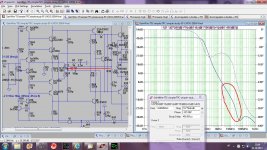
Nobody asked me about the compensation I used in this CFA amp, so I decided to explain why I did it in that way.
First I wanted to include lateral OPS in to compensation as per Cherry and this is first picture how it was connected and the loop gain I’ve got from it. Overall distortion was much lower this way than if the compensation was taken from the VAS/TIS output. It includes a shunt compensation too in the circle on the schematic. The loop gain was not high enough at 20 kHz, I wanted it the same as at 1 kHz. Look also how the down slope is wobbling, giving quite low gain margin.
BR Damir
Attachments
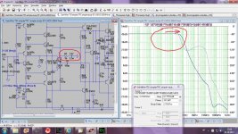
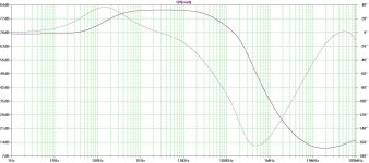
And finally third, improvement of the loop gain wobble below zero gain. Modification of the shunt compensation, instead to connect it to the ground it is connected back to the VAS/TIS input, arrow at the schematic. I this way I’ve got stable amp with low enough distortion.
BR Damir
BR Damir
Attachments
Nobody asked me about the compensation I used in this CFA amp, so I decided to explain why I did it in that way.
First I wanted to include lateral OPS in to compensation as per Cherry and this is first picture how it was connected and the loop gain I’ve got from it. Overall distortion was much lower this way than if the compensation was taken from the VAS/TIS output. It includes a shunt compensation too in the circle on the schematic. The loop gain was not high enough at 20 kHz, I wanted it the same as at 1 kHz. Look also how the down slope is wobbling, giving quite low gain margin.
BR Damir
Undoubtedly well studied.
- Home
- Amplifiers
- Solid State
- 200W MOSFET CFA amp