Hi Dadod, hope doing great. I got a chance to work on my DIY stuff today. Checked the power supply regulator again and its output voltage was +/-52.8 Vdc. The unregulated input is +/-57.6 Vdc. I was expecting that it should still maintain to +/-50 Vdc output, even though the input will go up 2Vdc higher?
I also started populating the amp board but I just realize that I was not able to buy BC560 because its no longer available. Can I use BC557? It seems like the specs are the same except the (NF) Noise figure. Also, use KSA992 and KSC1845 in replacement of 2SA970 and 2SC2240. Your Amp parts are getting obsolete. Hope these replacement parts still works.
Getting ready to power up and check voltages on R5 and R6.
Hi Fred,
This PS regulator is not fixed voltage regulator, it i a kind of capacitor multiplier, it just gos up or down with the input voltage. +/-52.8 V is still OK for this amp, you will get a bit more output power.

It looks like all trough hole transistor is going to disappear.
You can use BC559/BC549 all C grade or BC327/BC337 all 40 grade but not BC557.
What's the reason I can't use BC557? I have ten of these from previous projects. Based on the datasheet,
BC557/BC560 - collector - base voltage -50V
BC557/BC560 - collector - Emitter voltage -45V, and the rest of the specs are the same.
Is it because of the Noise figure? Oh boy, I have to wait another week again just to order BC549/BC559. BC327 is also obsolete.
Dadod, any other things I need to be aware of before placing the order? I should have ordered the transistors from you when I ordered the board. Seems like you still have a lot of these but I think its too late. I put together many amplifiers but this is the amp that took me too long. Maybe I'm getting old. Thanks for your quick reply.
BC557/BC560 - collector - base voltage -50V
BC557/BC560 - collector - Emitter voltage -45V, and the rest of the specs are the same.
Is it because of the Noise figure? Oh boy, I have to wait another week again just to order BC549/BC559. BC327 is also obsolete.
Dadod, any other things I need to be aware of before placing the order? I should have ordered the transistors from you when I ordered the board. Seems like you still have a lot of these but I think its too late. I put together many amplifiers but this is the amp that took me too long. Maybe I'm getting old.
Thanks for your quick reply.What's the reason I can't use BC557? I have ten of these from previous projects. Based on the datasheet,
BC557/BC560 - collector - base voltage -50V
BC557/BC560 - collector - Emitter voltage -45V, and the rest of the specs are the same.
Is it because of the Noise figure? Oh boy, I have to wait another week again just to order BC549/BC559. BC327 is also obsolete.
Dadod, any other things I need to be aware of before placing the order? I should have ordered the transistors from you when I ordered the board. Seems like you still have a lot of these but I think its too late. I put together many amplifiers but this is the amp that took me too long. Maybe I'm getting old.
I never used BC557 in this position, but if you like to try, in my opinion it should be paired with BC547 not BC550.
I must have paired BC 546/556, 547/557, 550/560, 549/559, any which way, according to availability in my stock in several power supply builds, particularly series pass regulators and capacitance multipliers. Except for gain variations and consequently different settings of trimpots to set output voltage, the combinations make no difference.
Using the correct complementary pair in amplifier and preamplifier builds is another matter altogether. I try to match hfe on opposite sides, as much as I can.
Using the correct complementary pair in amplifier and preamplifier builds is another matter altogether. I try to match hfe on opposite sides, as much as I can.
Thanks Guys for your advice. I found my Extreme-A amp that never been finished. This been laying around for more than 10 years and didn't finish due to CRD J511 issue, no longer available, power supply went bad and got discourage. Also, need a big heat sink and according to some successful builders, its a very heavy amp.
Anyways, I found out that it uses BC547 and BC557 transisors. So for the mean time, I will cannibalize those parts and put it on Dadod's amp until I get my order for BC549/BC559. I hope I will get some time to work on this project this weekend.
Anyways, I found out that it uses BC547 and BC557 transisors. So for the mean time, I will cannibalize those parts and put it on Dadod's amp until I get my order for BC549/BC559. I hope I will get some time to work on this project this weekend.
Hi Damir: I finally got around to the build. PS works great; with the 40VAC nominal windings, gives me 55V regulated - I assume this is OK.
I matched the Q11/Q12 and Q3/Q4 on Vbe, but still got quite different (and a bit too high on the V- side) currents through R5/R6. Got it to 1.58mA on both sides by changing R4 to 750 ohm and R7 to 910 Ohm, then adjusting the P2 - is this OK?
Thank you!
I matched the Q11/Q12 and Q3/Q4 on Vbe, but still got quite different (and a bit too high on the V- side) currents through R5/R6. Got it to 1.58mA on both sides by changing R4 to 750 ohm and R7 to 910 Ohm, then adjusting the P2 - is this OK?
Thank you!
Hi ydrozd, just curious what transistor did you use? I end up with BC547/BC557 for the meantime.
I got the chance to power up the board yesterday and the voltage at R5 goes up and down from 1.8 - 1.9V, with the volatge output at the regulator +/- 52.7Vdc. On R6 1.7 - 1.8V, so 0.1V difference which I think might not be a big deal. The LED was match 1.78V, but I was curious so I replaced D11 with 1.75V LED and the voltage became balance to 1.8V - 1.9V.
I got the chance to power up the board yesterday and the voltage at R5 goes up and down from 1.8 - 1.9V, with the volatge output at the regulator +/- 52.7Vdc. On R6 1.7 - 1.8V, so 0.1V difference which I think might not be a big deal. The LED was match 1.78V, but I was curious so I replaced D11 with 1.75V LED and the voltage became balance to 1.8V - 1.9V.
Hi ydrozd, just curious what transistor did you use? I end up with BC547/BC557 for the meantime.
I got the chance to power up the board yesterday and the voltage at R5 goes up and down from 1.8 - 1.9V, with the volatge output at the regulator +/- 52.7Vdc. On R6 1.7 - 1.8V, so 0.1V difference which I think might not be a big deal. The LED was match 1.78V, but I was curious so I replaced D11 with 1.75V LED and the voltage became balance to 1.8V - 1.9V.
I have a stash of BC550C/BC560C, that's what I used. The voltage across R5/R6 - after I changed R4/R7 to 750R/910R respectively is now stable at 1.9. LEDs are matched at 1.8V.

Hi Damir: I finally got around to the build. PS works great; with the 40VAC nominal windings, gives me 55V regulated - I assume this is OK.
I matched the Q11/Q12 and Q3/Q4 on Vbe, but still got quite different (and a bit too high on the V- side) currents through R5/R6. Got it to 1.58mA on both sides by changing R4 to 750 ohm and R7 to 910 Ohm, then adjusting the P2 - is this OK?
Thank you!
Hi ydrozd,
It looks that your transistors are not so well matched, or LEDs
, if you need to have that difference in in R4/R7 resistors. It still should work as it is and yes you then adjust output DC offset with P2, but without DC serve opamp in its socket. When all is set then insert DC servo opamp and it should dell with the rest of the DC offset.Dadod, I don't have MURS320 DO-201AD for D1, D2 and no longer available too except the SMD version. I have MR852RLG, 200V - 3A. Vf -forward volatge is 1.04V while MUR320 Vf -890 mV. Is that ok to use for substitute?
Yes, this diode just protect from revers voltage here.
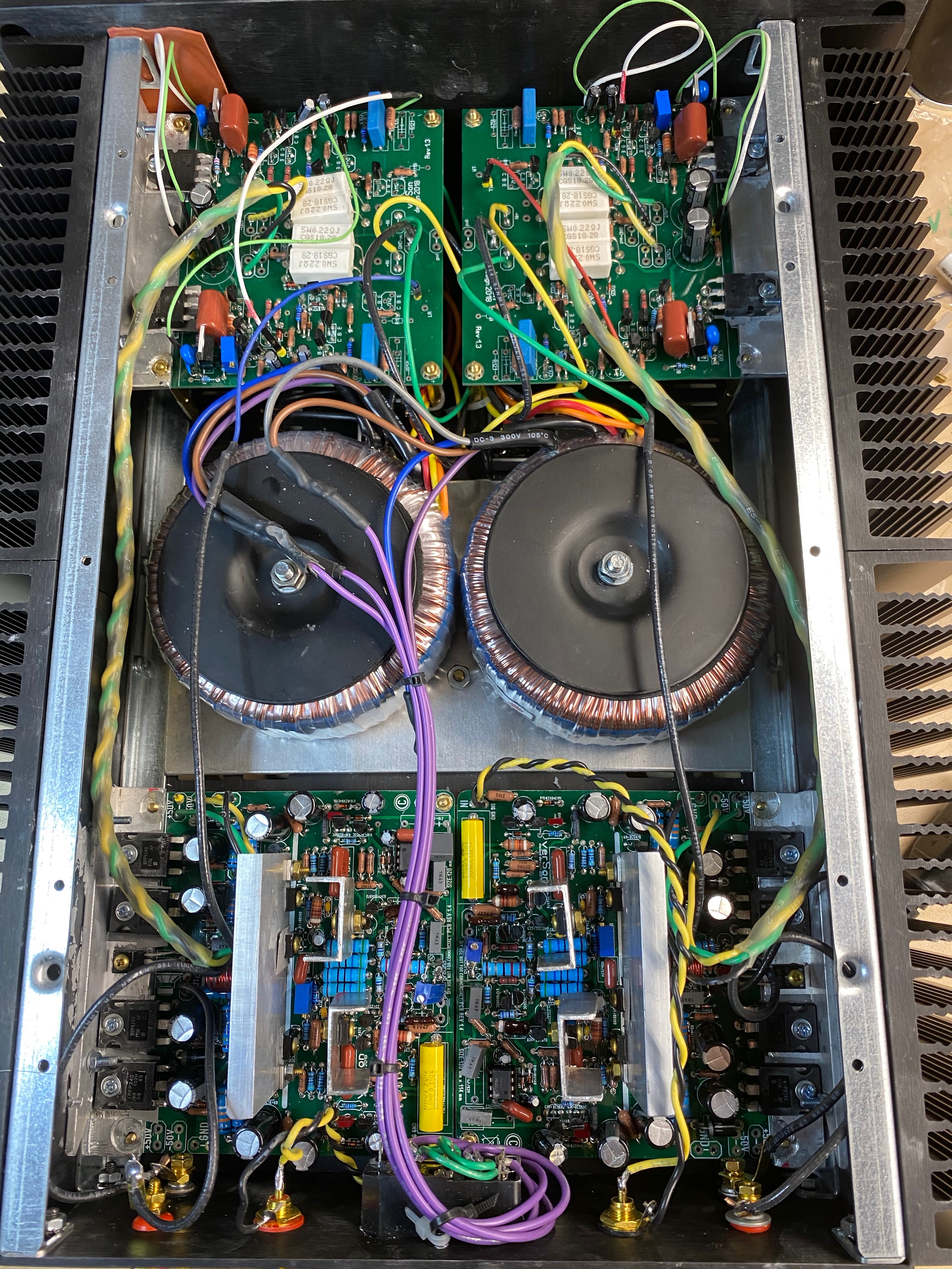
Good job Ydrozd! Congratulation! That's a dual mono.
I haven't got much progress on mine. Been busy but I was able to experiment a bit with the input stage bias this weekend. When I use BC547/557, the IPS bias goes up to 1.9Vdc after 15 minutes. When I switched to BC549/559, the voltage went down to 1.79Vdc and the other channel was only 1.76Vdc. I hope this unbalanced voltage between amp is not a big deal.
Even though, hfe is match and LED, measurement on +/- is not exactly the same, I have to replace the 820R to 845 on the positive side. Also have to rotate the P2 to make it stable.
Dadod, is it really necessary to put heatsink on the drivers? I know the 200W needs it but for 100W, I assume not needed. Correct me if I'm wrong. Don't have a heatsink right now that will fit on the board.
Good job Ydrozd! Congratulation! That's a dual mono.
I haven't got much progress on mine. Been busy but I was able to experiment a bit with the input stage bias this weekend. When I use BC547/557, the IPS bias goes up to 1.9Vdc after 15 minutes. When I switched to BC549/559, the voltage went down to 1.79Vdc and the other channel was only 1.76Vdc. I hope this unbalanced voltage between amp is not a big deal.
Even though, hfe is match and LED, measurement on +/- is not exactly the same, I have to replace the 820R to 845 on the positive side. Also have to rotate the P2 to make it stable.
Dadod, is it really necessary to put heatsink on the drivers? I know the 200W needs it but for 100W, I assume not needed. Correct me if I'm wrong. Don't have a heatsink right now that will fit on the board.
Yes you need that drivers heatsink and there is one half of the bias spreader as part of the thermal compensation. There are two transistors in the bias spreader, one fixed on the main heatsink and other on the drivers heatsink.
Have a nice building. By the way no problem with that voltage unbalance, it will be sorted with negative feedback.
Damir
Done with the build - sounds fantastic on first listen, will do some critical listening over the weekend. Thank you Damir!
Biased at 130ma, doesn't get all that hot - I may try to raise it a bit.
An externally hosted image should be here but it was not working when we last tested it.
Very nice build and I'am glad you like the sound.
Bay the way you don't need those small VAS heatsinks, but if you like to keep them that's OK.
Last edited:
Very nice build and I'am glad you like the sound.
Bay the way you don't need those small VAS heatsinks, but if you like to keep them that's OK.
Yeah; I read in earlier posts that someone had 10ma flowing through, making VAS heat up, and since I had these handy, I figured it wouldn't hurt. Turned out in my build it is more like 4.5ma, but since I already hat them...
Anywhay, did some more listening. This is absolutely stunning. Specifically, Vivaldi Le Quattro Stagioni 180g 45rpm (Giuliano Carmignolas & Sonatori de la Gioiosa Marca).
Compared with my aging Krell KAV-300i, the higher register violins are amazingly clear. It wasn't too bad with Krell, but this is in a new league. Sounstange is rock solid (well, no surprise as my build is dual mono).
Equipment:
Music Hall Ikura turntable
Ortofon 2m Blue MMC
RJM Emerald phono stage
Mezmerise B1 buffer
DIY speakers, Audax (A651)
Thank you for this quite detailed evaluation.
Regarding VAS current, I found that for this mosfet OPS, to keep it between 4 and 6 mA is good enough, no need for high as 10mA or even higher.
BR Damir
Hi Dadod,
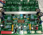
I was able to complete soldering the OPS components today, including drilling and tapping the heatsink. That took some amount of time to get it done.
Powered up and did the VAS measurement, (R14 - R52) started at .525 Vdc and keeps on rising till it reached .635 Vdc. The heatsink temperature of Q5, Q7 & Q1 goes up to 50C. Q6 & Q8 temp also goes up to 50C. I think its too hot. Can I increase the R14 & R52 to 120 ohms to lower down the current a bit?
Maybe this is the effect of using BC559 instead BC560?
I also tried to set the transistor bias to .03 V or 130 mA but after a while it start to drop. What is the proper way of adjusting the bias? when the heatsink already hot? Mine would probably take a while since its a big heatsink.
The DC offset goes up and down 8.3mv to 15mv without the op amp. With op amp installed, -2.5mv to 6.7mv. Is the fluctuation on the DC offset normal on this amp? I know some other amp also fluctuates too. But some are more steady.
- Home
- Amplifiers
- Solid State
- 200W MOSFET CFA amp