Centre of the wiring looks best to me, though to me going
directly from here to each capacitor will be better than via a T.
There can only be one............. earth / ground.
Some of your measurement problems will be due to a ground
loop if the negative of your test gear is connected to earth.
 sreten.
directly from here to each capacitor will be better than via a T.
There can only be one............. earth / ground.
Some of your measurement problems will be due to a ground
loop if the negative of your test gear is connected to earth.
Something is definitely not right!
Well I checked the pc and yep the case is earthed, and more importantly the line out is earthed. Maybe I'll have to get a two pin power lead for doing testing........
Also I rewired the earth wiring (and in the process also discovered there were in fact two connections to the chassis from the star ground, one on the base, one on the back (the one on the back supposed to be insulated from the case, but not!). Changed to your Doug Self recommended config. Subjectively I couldn't tell any difference, and If anything at full volume the hum seems worse than the very original wiring (but more on that in a bit).... Objectively I think the rmma test shows a cleaner result in the higher frequencies, and more even noise (ie same in both channels).
However!!!! I think All of this testing has stressed some component that was on the way out. I reset my queisiant current to 99mA (supposed to be 100, but was having difficulty getting it exact) one channel was sitting on about 101, the other 107 prior to this. When I went to retest I couldn't get the decent levels out of rmaa and the mosfets on the right channel were making a pulsing singing noise in time with the pulses that rmaa puts out (and getting very hot)..... I reset the quiesiant current to 110 mA and that problem went away (at least at lower volume settings), but the distortion was worse, and the right channel was approximately 10 times higher distortion than the left.
I then did the earth changes and have just redone the measurements. The THD has gone through the roof. Take a look at the latest measurements:
http://home.swiftdsl.com.au/~tonywww/rmaa/series200_optimal_earth.htm
Obviously the change to the earth wiring hasn't caused this, but I definitely have some debugging to do Time for that blanket cap changeout I think!
Tony.
Well I checked the pc and yep the case is earthed, and more importantly the line out is earthed. Maybe I'll have to get a two pin power lead for doing testing........
Also I rewired the earth wiring (and in the process also discovered there were in fact two connections to the chassis from the star ground, one on the base, one on the back (the one on the back supposed to be insulated from the case, but not!). Changed to your Doug Self recommended config. Subjectively I couldn't tell any difference, and If anything at full volume the hum seems worse than the very original wiring (but more on that in a bit).... Objectively I think the rmma test shows a cleaner result in the higher frequencies, and more even noise (ie same in both channels).
However!!!! I think All of this testing has stressed some component that was on the way out. I reset my queisiant current to 99mA (supposed to be 100, but was having difficulty getting it exact) one channel was sitting on about 101, the other 107 prior to this. When I went to retest I couldn't get the decent levels out of rmaa and the mosfets on the right channel were making a pulsing singing noise in time with the pulses that rmaa puts out (and getting very hot)..... I reset the quiesiant current to 110 mA and that problem went away (at least at lower volume settings), but the distortion was worse, and the right channel was approximately 10 times higher distortion than the left.
I then did the earth changes and have just redone the measurements. The THD has gone through the roof. Take a look at the latest measurements:
http://home.swiftdsl.com.au/~tonywww/rmaa/series200_optimal_earth.htm
Obviously the change to the earth wiring hasn't caused this, but I definitely have some debugging to do
Tony.
Well I checked the pc and yep the case is earthed, and more importantly the line out is earthed. Maybe I'll have to get a two pin power lead for doing testing........
Only for other equipment that is earthed,
Hi Sreten,
The soundcard preamp (in between the sound card and the amp's speaker outputs) is running off a 12V battery and isn't earthed. So the sheild on the rca lead leading from amp to sound card is earthed through the mains at both ends, but these are the only two earth points.
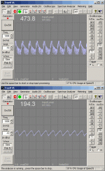
I just decided to measure the ripple on the PS. Not sure if this indicates I've stuffed something up, or maybe one of my PS caps is dud, but the difference between -ve and +ve rails is quite severe (could also be a result of whatever nastiness is going on with the right channel). The search continues
Test done as before in previous thread, with amp cranked to just before clipping, 1Khz signal as input, 7.5 Ohm load resistors.
edit: +ve rail is the top one.
edit: Also with no input signal the ripple on the -ve rail is about 33mV and on +ve is about 342mV. Something nasty going on here I think.
Tony.
Attachments
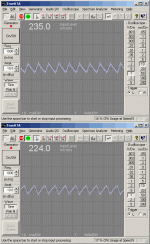
Well I've fixed the ripple problem. Though I really don't know what did it. All I did was test the PS without the amp connected virtually no ripple (like about 0.5 mV) same again with a 25W 240V bulb connected as a load (about 9mV ripple). A 25W 240V bulb is great for de-energising power supply caps BTW......
Then I connected each channel up in turn and tested with a load and both behaved nicely, finally I connected both channels back up and tested and the horrible ripple on the +ve rail went away. I can only guess I had a dud solder joint somewhere in the PS, and all the unsoldering and resoldering fixed it....... Pretty strange though since this ripple problem has been there through Two previous power supply rewirings......
Also today (after having to debug the input switching logic, which decided to die) I changed the earth wire back to running from the star point to the earth lug, and my distortion problem went away. I only did this as I was measuring voltages around the amp and found the supply rails were only registering 33V (instead of 63V) when I measured with the negative probe on the case. I was seeing no resistance between the case and 0V but that was the measurement. Could be that the lug I soldered to had a very slight resistance but I don't know. Anyway the distortion problem went away so I'm not going to complain.
Have decided to call it quits until I buy all of the replacement caps for the power amp, then I'll have another go.
Pic of PS ripple attached:
latest measurements (although maybe not quite as good as before)
http://home.swiftdsl.com.au/~tonywww/rmaa/series200_earth_3.htm
It's funny but the thing I am most unhappy about with the amp, is actually the only part of the rmaa test that receives an excellent rating I guess that's mainly because one channel is much worse than the other, so I know it should be able to do better.
Tony.
Then I connected each channel up in turn and tested with a load and both behaved nicely, finally I connected both channels back up and tested and the horrible ripple on the +ve rail went away. I can only guess I had a dud solder joint somewhere in the PS, and all the unsoldering and resoldering fixed it....... Pretty strange though since this ripple problem has been there through Two previous power supply rewirings......
Also today (after having to debug the input switching logic, which decided to die) I changed the earth wire back to running from the star point to the earth lug, and my distortion problem went away. I only did this as I was measuring voltages around the amp and found the supply rails were only registering 33V (instead of 63V) when I measured with the negative probe on the case. I was seeing no resistance between the case and 0V but that was the measurement. Could be that the lug I soldered to had a very slight resistance but I don't know. Anyway the distortion problem went away so I'm not going to complain.
Have decided to call it quits until I buy all of the replacement caps for the power amp, then I'll have another go.
Pic of PS ripple attached:
latest measurements (although maybe not quite as good as before)
http://home.swiftdsl.com.au/~tonywww/rmaa/series200_earth_3.htm
It's funny but the thing I am most unhappy about with the amp, is actually the only part of the rmaa test that receives an excellent rating
Tony.
Attachments
- Status
- This old topic is closed. If you want to reopen this topic, contact a moderator using the "Report Post" button.

