Hi All,
After a successful mod to my sound card preamp today, I decided to use it as a buffer to allow me to test my trusty old playmaster series 200 amp using RMAA 5.2.
I'm not 100% sure about my methodology, but what I did was:
1. a loopback test on the sound card.
2. a test on the soundcard preamp. (so I have a baseline)
3. ran tests on the amp (with 7.5 ohm resistive loads). I took the input to the preamp off the resistors and had the preamp set to divide by 10 to limit the voltage getting to my sound card. The results were a bit disturbing")
results of the tests on sound card and preamp here (including the improvement of changing the 10nf coupling cap on the preamp to 68nF, thanks Sreten)....RightMark Audio Analyzer test: comparison http://home.swiftdsl.com.au/~tonywww/rmaa/preamp_compare_MKII.htm All looks fine.
some results of testing the amp here: http://home.exetel.com.au/wintermute/rmaa/series_200_pre_vs_whole_amp.htmhttp://home.swiftdsl.com.au/~tonywww/rmaa/series_200_pre_vs_whole_amp.htm
Note that the amp is an integrated amp, but I disconected the preamp stage and measured it separately to isolate where problems were coming from, the second set of results is running through the full amp.
The main thing I'm concerned about here is the very poor crosstalk result.
Can anyone make a suggestion where to look for the source of the crosstalk (I'm guessing power supply)?
I already asked some questions before about this amp here:
http://www.diyaudio.com/forums/showthread.php?s=&threadid=19626&highlight= and haven't yet acted on the suggestions (mainly to replace all the electros as they are now 16+ years old).
The other thing I noticed is the pattern to the noise (ignore the 50Hz bump it's in the soundcard preamp), starting at 100Hz and every 50 Hz after that (up to about 4K) there is a spike, I'm assuming that this is comming from the power supply, I know its at a pretty low level, but I'd like to get rid of it if I can.
I previously posted about the PS here:
Power supply problem??? - diyAudio
Tony.
After a successful mod to my sound card preamp today, I decided to use it as a buffer to allow me to test my trusty old playmaster series 200 amp using RMAA 5.2.
I'm not 100% sure about my methodology, but what I did was:
1. a loopback test on the sound card.
2. a test on the soundcard preamp. (so I have a baseline)
3. ran tests on the amp (with 7.5 ohm resistive loads). I took the input to the preamp off the resistors and had the preamp set to divide by 10 to limit the voltage getting to my sound card. The results were a bit disturbing
results of the tests on sound card and preamp here (including the improvement of changing the 10nf coupling cap on the preamp to 68nF, thanks Sreten)....RightMark Audio Analyzer test: comparison http://home.swiftdsl.com.au/~tonywww/rmaa/preamp_compare_MKII.htm All looks fine.
some results of testing the amp here: http://home.exetel.com.au/wintermute/rmaa/series_200_pre_vs_whole_amp.htmhttp://home.swiftdsl.com.au/~tonywww/rmaa/series_200_pre_vs_whole_amp.htm
Note that the amp is an integrated amp, but I disconected the preamp stage and measured it separately to isolate where problems were coming from, the second set of results is running through the full amp.
The main thing I'm concerned about here is the very poor crosstalk result.
Can anyone make a suggestion where to look for the source of the crosstalk (I'm guessing power supply)?
I already asked some questions before about this amp here:
http://www.diyaudio.com/forums/showthread.php?s=&threadid=19626&highlight= and haven't yet acted on the suggestions (mainly to replace all the electros as they are now 16+ years old).
The other thing I noticed is the pattern to the noise (ignore the 50Hz bump it's in the soundcard preamp), starting at 100Hz and every 50 Hz after that (up to about 4K) there is a spike, I'm assuming that this is comming from the power supply, I know its at a pretty low level, but I'd like to get rid of it if I can.
I previously posted about the PS here:
Power supply problem??? - diyAudio
Tony.
Last edited:
I would presume the PA cross talk performance is due to the
channels sharing the resistance of a common ground return path.
The CD input looks like classic capacitive coupling behaviour.
I'm not too sure about your other results. You say the board
follows a star earthing topoloogy, but I suspect an innapropriate
Star earthing point, which should not be on the actual circuit
board. The board should have several seperate ground connections
back to the star point.
sreten.
channels sharing the resistance of a common ground return path.
The CD input looks like classic capacitive coupling behaviour.
I'm not too sure about your other results. You say the board
follows a star earthing topoloogy, but I suspect an innapropriate
Star earthing point, which should not be on the actual circuit
board. The board should have several seperate ground connections
back to the star point.
sreten.hmmm I was worried it would be some design "feature"
Well you pretty much guessed right on the way the star earthing is done. Now I have to decide do I butcher it or not!!!! Any parts in particular I should pay more attention to (apart from separating left and right!) Maybe some really big wire from the circuit board back to the earth point
The preamp section has a 56nF cap in it which I would say explains the slightly earlier rolloff at the low end than the sound card preamp, I'm not so sure about the high end rolloff though. The only cap in the signal path to the main amp section is a 1uF.
One thing that was kinda weird with the crosstalk was that it got worse as I increased the power (best result I got was about 65db) worst was 29db! (I'm assuming due to the common ground resistance) The strange part however was that when I bypassed the preamp, and fed the amp directly off the soundcard, the crosstalk was the same at 31.5db at low and high ampification levels (basically I used volume control in windows and used 1X and 0.1X settings on preamp.
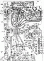
Attached is a scan of the circuit board layout showing the "star" earthing.
Tony.
Well you pretty much guessed right on the way the star earthing is done. Now I have to decide do I butcher it or not!!!! Any parts in particular I should pay more attention to (apart from separating left and right!) Maybe some really big wire from the circuit board back to the earth point
The preamp section has a 56nF cap in it which I would say explains the slightly earlier rolloff at the low end than the sound card preamp, I'm not so sure about the high end rolloff though. The only cap in the signal path to the main amp section is a 1uF.
One thing that was kinda weird with the crosstalk was that it got worse as I increased the power (best result I got was about 65db) worst was 29db! (I'm assuming due to the common ground resistance) The strange part however was that when I bypassed the preamp, and fed the amp directly off the soundcard, the crosstalk was the same at 31.5db at low and high ampification levels (basically I used volume control in windows and used 1X and 0.1X settings on preamp.
Attached is a scan of the circuit board layout showing the "star" earthing.
Tony.
Attachments
Nah I just disconnected the preamp section from the poweramp to do testing. What I am thinking though is at a minimum, I could cut the tracks on the Speaker Earth returns and run separate heavy duty wires back to the star point on the chassis.
I'm assuming that would be the major source of current flowing to earth in the amp. I reckon I can do that reasonably safely without stuffing anything up too majorly
Tony.
I'm assuming that would be the major source of current flowing to earth in the amp. I reckon I can do that reasonably safely without stuffing anything up too majorly
Tony.
Hmmmmmmm...... The rectifier and filter caps are on the base of the chassis with the ground on the filter caps going to the chassis earth point and the star point on the circuit board goes to the same earth point. (not obvious from previous posts).
Wouldn't cutting the track (so there are no loops) and wiring back to that same chassis point be effectively the same thing as having the current flow through the circuit board and and then back through the wire, to the same point on the chassis? Or am I missing something fundamental here?
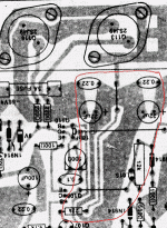
Just looking at the circuit board diagram, I think I have just spotted a loop in the main earthing!!! (although both branches end up back at the same point...... probably nothing but may be worth fixing
Tony.
edit: attached the bit I'm talking about circled.
Wouldn't cutting the track (so there are no loops) and wiring back to that same chassis point be effectively the same thing as having the current flow through the circuit board and and then back through the wire, to the same point on the chassis? Or am I missing something fundamental here?
Just looking at the circuit board diagram, I think I have just spotted a loop in the main earthing!!! (although both branches end up back at the same point...... probably nothing but may be worth fixing
Tony.
edit: attached the bit I'm talking about circled.
Attachments

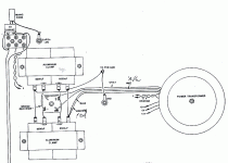
Ok here is a pic of the PS wiring (very basic PS)
1st I think I'll run the earth from the filter caps to chassis ground instead of the pcb?
2nd assuming point one is valid should I have a separate wire from each cap to the chassis ground rather than the way it is wired now?
3rd what's with the 0.01 uF cap wired accross the mains switch? is it to filter switch contact bounce?
4th should the transformer center tap go to the caps as shown or to the chassis?
hmmm I keep editing....
5th should the mains earth be to a separate point on the chasis to the main ground point?
Tony.
Attachments
changed the filter caps ground wire
Ok I simply removed the lead from the caps to the star ground on the pcb, shortened the lead significantly and soldered it direct to the chassis earth lug. Didn't change anything else.
The result? Better noise performance especially over 4Khz! and slightly better distortion performance (but I suspect that this is simply due to the lower noise since the test tone is 1Khz and there were noise peaks at 2Khz, 3Khz, 4Khz etc).
Note that I also shortened the leads I had running to my load resistors from about 3M to about 10cm, I tested before and after doing this and the only change was that the crosstalk improved by about 6db.
Tommorow if I have time (and energy) after Christmas shopping, I'll buy some decent wire and maybe redo the rest of the power supply wiring. First uprating the wire from the star point back to the earth lug. The existing wiring is super flexible 512 strand wire which is basically as far as I know the sort of wire they use in multimeter leads. I'm going to get some 7 x 95/0.12mm strand 8ag OFC and use that instead.
Results of the latest test here: http://home.swiftdsl.com.au/~tonywww/rmaa/series200_earth_mod1.htm
Note that "amp only" means I bypassed the preamp stage and fed the soundcard straight into the 1uF cap at the input of the power amp.
Tony.
Well according to my amplifier handbook (D.Self) the
earth lug is correct but the chassis ground is wrong.
According to the above the chassis should be connected
to the ground at the inputs and at no other points.
I wouldn't call that small section a ground loop at all,
and cutting the track will not help.
sreten.
earth lug is correct but the chassis ground is wrong.
According to the above the chassis should be connected
to the ground at the inputs and at no other points.
I wouldn't call that small section a ground loop at all,
and cutting the track will not help.
sreten.Strange, I've always been told that the inputs should be isolated from the chassis...... Maybe I'm not visuallising this correctly
I think I'm refering to the earth lug and the chassis ground as being the same thing, chassis basically being the case of the amp, have I got the terminology wrong? woops just noted that my diagram shows both the earth lug and the gnd lug, and I did ask about it.... so the mains earth is ok, but the star ground on the pcb shouldn't be connected back to the chassis lug????? That sounds strange to me....... especially since just about everything I've read about star grounding (admittedly not much) says to keep the large currents as far from your input ground as possible.
I think I'll just try some stuff (not too radical, at least not yet...) and measure and listen to what difference positive or negative (if any) it makes.
Oddly after doing the last measurements, I went downstairs and hooked the speakers back up, and the left channel was noticably quieter (especially in the tweeter), the noise from the tweeter changed from a sort of muli freq hum to a low hiss) but the right channel has not improved at all.....
The weird thing is that on examining the noise graphs from rmaa It doesn't look like one channel is consistantly worse than the other (the noise doesn't coincide the plots continually intersect one another one higher at one point then it swaps to the other) the differences in magnitude are one or two db at most (around the -120db mark) Note that in order to here this my ear needs to be within about 20cm of the drivers, so it's not really that big a deal, it basically annoys me (especially now that its much worse on one channel than the other!)
Yeah I kind of figured that the bit I thought might be a ground loop was a bit far fetched wishfull thinking on my part, ultimately either way the current is finding the same way to ground.
Tony.
I think I'm refering to the earth lug and the chassis ground as being the same thing, chassis basically being the case of the amp, have I got the terminology wrong? woops just noted that my diagram shows both the earth lug and the gnd lug, and I did ask about it.... so the mains earth is ok, but the star ground on the pcb shouldn't be connected back to the chassis lug????? That sounds strange to me....... especially since just about everything I've read about star grounding (admittedly not much) says to keep the large currents as far from your input ground as possible.
I think I'll just try some stuff (not too radical, at least not yet...) and measure and listen to what difference positive or negative (if any) it makes.
Oddly after doing the last measurements, I went downstairs and hooked the speakers back up, and the left channel was noticably quieter (especially in the tweeter), the noise from the tweeter changed from a sort of muli freq hum to a low hiss) but the right channel has not improved at all.....
The weird thing is that on examining the noise graphs from rmaa It doesn't look like one channel is consistantly worse than the other (the noise doesn't coincide the plots continually intersect one another one higher at one point then it swaps to the other) the differences in magnitude are one or two db at most (around the -120db mark) Note that in order to here this my ear needs to be within about 20cm of the drivers, so it's not really that big a deal, it basically annoys me (especially now that its much worse on one channel than the other!)
Yeah I kind of figured that the bit I thought might be a ground loop was a bit far fetched
wishfull thinking on my part, ultimately either way the current is finding the same way to ground.Tony.
I think I'm refering to the earth lug and the chassis ground as being the same thing, chassis basically being the case of the amp, have I got the terminology wrong? woops just noted that my diagram shows both the earth lug and the gnd lug, and I did ask about it.... so the mains earth is ok, but the star ground on the pcb shouldn't be connected back to the chassis lug????? That sounds strange to me....... especially since just about everything I've read about star grounding (admittedly not much) says to keep the large currents as far from your input ground as possible.
You would need to reconnect the PCB GND wire for the star ground.
Disconnect the ground lug, but not the earth lug.
Connect the chassis to PCB GND at the input requiring lowest noise.
There will be no large currents in this input ground.
sreten.Yes I was wondering about that. I'm going to test it with no load resistors and see what the result is.
The other thing I wonder is whether it is the power supply. The fact that when I input a 1Khz sine wave, the ripple on the power supply has the 1Khz sine wave superimposed on it, makes me suspicious.
Also when I did a test at low volume (bumped up the gain on the soundcard to get an ok level) the crosstalk was around -65db which is much better.
certainly if I listen to music with very strong channel separation I don't hear any leakage from one channel to the other.
When I was testing with the soundcard directly connected to the amp, something was "singing" there was a high pitched noise bit like a very high tuning fork coming from somewhere in the amp, couldn't pinpoint where, and didn't want to leave it that way for too long in case something cooked (the load resistors were already getting too hot...... maybe that's part of the problem)....
Tony.
edit: Just tryed another test. I connected only the left channel of my dvd player, connected the right channel speaker to the B speaker output, selected speakers B and listened. At normal listening volume the music could be heard very faintly in the right speaker at full volume it was still probably 1/4 of the volume I would normally listen at, also was mainly in the upper freq range, no bass or mid bass). I'll try again with the resistor in place of the left speaker so that there is actually a load on the left channel when doing the test. But first I have to go shopping bah humbug
sreten said:
You would need to reconnect the PCB GND wire for the star ground.
Disconnect the ground lug, but not the earth lug.
Connect the chassis to PCB GND at the input requiring lowest noise.
There will be no large currents in this input ground.
I don't understand this..... If I disconnect the existing star earth connection and instead connect it to the input ground, then ALL other currents will then be redirected back through the ground at the inputs to the chassis earth, and all of a sudden you DO have large earth currents at the input??????
Tony .... confused

latest tests
Ok,
I tried the listening test with and without dummy load on left channel with only the dvd left channel connected. at all but very high volumes, switching in the dummy load caused a very slight increase in the volume comming from the right channel speaker. If pushed to the point just before clipping the change was more noticable. If I pushed it way past clipping the sound from the right channel became quite a bit louder and very distorted. Note that at full volume without the dummy load on the left channel the sound from the right channel was not distorting. From this I'm tempted to conclude that the problem lies with the power supply.
I also did the rmaa test again without the dummy load, result was that the stereo crosstalk figure improved to -79.2db quite respectable really, I would again say probably an indication of power supply weakness.
If I have time tonight I'll re-wire the power supply and test again. Also interestingly the marked difference in noise levels between the left and right channels is now showing up in rmaa. could be something I've desoldered and resoldered while separating stages of the amp. All tests from now on, I'm going to do through both preamp and power amp sections, treating the amp as a whole.
If I get really adventurous I may pull out the spare 300VA torroidal I have, only prob is I don't have any filter caps to use with it, and buying a set as an experiment is a little bit expensive! I guess I could parralel up the two windings on each and use one torroidal for -ve rail and one for the +ve rail. At least that way I wouldn't need any more caps, and I'd have twice the current at my disposal
Tony.
Well I rewired the power supply and if nothing else I learned that 8 gauge wire is a b*tch to work with, probably should have got the 12 gauge!
Having said that after only changing the wire between the caps and the rectifier, and changing the way the wire linked back to the earth point, and finally changing the main wire from the star ground on the pcb to the chassis ground to 8 gauge, the crosstalk with the load resistors improved from -37.5db to -43.5db, another 6db improvement...... what is it with 6db
Still not real good but at least it's an improvement. The downside is that the noise got worse (probably not surprising when fiddling with the ground wiring....... I don't think moving the 0V wires from the xformer was such a good idea..... I'll move it back and hopefully it will go back to previous noise levels. When I say got worse, it's only noticably worse when the amp is cranked right up with no signal (and rmaa shows signs of the high freq noise comming back..... Oh well maybe I'll get somewhere tomorrow
Tony.
wintermute said:
I don't understand this..... If I disconnect the existing star earth connection and instead connect it to the input ground, then ALL other currents will then be redirected back through the ground at the inputs to the chassis earth, and all of a sudden you DO have large earth currents at the input??????
Tony .... confused
The existing ground (chassis connection) is not the star point.
The star point is on the PCB and should connected via heavy
wire to the centre point (OV) of the power supply capacitors.
Heavy connections for the +/- rails will reduce rail ripple.
All the P.S. wiring should be heavy duty,
especially to and from the diode bridge.
The case should be connected to mains earth at the mains input.
The earth lug is correct.
The ground lug should be disconnected.
Asumming the case is single insulated mains earth and the star
point will now be not connected, but the amplifier works.
The case is connected to the star point with a short link to
the single ground return track next to the phono socket.
No extra operating currents will flow through the ground return.
(P.S. does your PC have a two wire or 3 wire mains connection ?)
sreten.Thanks sreten. I'll give that a try... Yes the pc has a 3 pin plug, I'm assuming that the case is grounded.
I guess thinking about it 0V is just a reference, and it doesn't have to be earth.... so the current flow will be back to 0V not to the earth point.
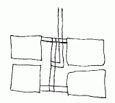
I wired up the 0V wiring on the caps as in the diagram thinking this should be better than the existing way. Should I put the ceter tap from the transformer to the centre of the 0V wiring or directly onto one of the caps? I'm leaning towards directly to a cap at the moment (its currently on the gnd lug)......
Tony.
edit: it's times like this I wish I had a digital camera
I guess thinking about it 0V is just a reference, and it doesn't have to be earth.... so the current flow will be back to 0V not to the earth point.
I wired up the 0V wiring on the caps as in the diagram thinking this should be better than the existing way. Should I put the ceter tap from the transformer to the centre of the 0V wiring or directly onto one of the caps? I'm leaning towards directly to a cap at the moment (its currently on the gnd lug)......
Tony.
edit: it's times like this I wish I had a digital camera
Attachments
- Status
- This old topic is closed. If you want to reopen this topic, contact a moderator using the "Report Post" button.
- Home
- Amplifiers
- Solid State
- The quest to fix my amp has begun!