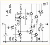
hello. i want to build one of those old style amplifiers with a single transistor as input stage . I searched the net and i found this circuit.
I would like to hear your comments and suggestions for similar circuits of the same topology...
I would like to hear your comments and suggestions for similar circuits of the same topology...
Attachments
Hmm - industrial power transistors for the output transistors. ELEKTOR?
This design may be intended for lowest cost rather than good sound. There is no guarantee that just incorporating a singleton input stage and bootstrapped capacitor VAS in an amplifier is going to result in good audio.
'Nice idea and might add a lot of 2nd harmonic distortion but that might be all.
This design may be intended for lowest cost rather than good sound. There is no guarantee that just incorporating a singleton input stage and bootstrapped capacitor VAS in an amplifier is going to result in good audio.
'Nice idea and might add a lot of 2nd harmonic distortion but that might be all.
PAnos consider your self a higher capacitor in the inpou 1ufd after a quick calculation but also an RF filter combination 2 resistors and one capcitor should also be in order .
Expect plenty of harmonics short of tubish sound with out the tube issues .You know all the secrets on pcb design so go ahead do it and let us know . ....
I presume that since we havent talk much for some time that you have your self a proper set of speakers by now ...
Kind regards
busy busy
Sakis
Expect plenty of harmonics short of tubish sound with out the tube issues .You know all the secrets on pcb design so go ahead do it and let us know . ....
I presume that since we havent talk much for some time that you have your self a proper set of speakers by now ...
Kind regards
busy busy
Sakis
If you want to build something with low distortion, low noise and acceptable frequency response... don't build that. I had one of those years ago and inspite of my best efforts, i couldn't make it sound even just OK. The problem was instability, if the comp cap was large enough to prevent oscillation, it killed the high frequencies. Tried re-routing the wiring, substituted tighter tolerance components, lowered the supply voltage but never could get anything close to real Hi-Fi sound. So I gave up and got rid of it, it was a total waste of time as far as I'm concerned. On the other hand, if you want to build it to learn something, then learn you will! Just don't expect too much from that design performance-wise.
Mike
Mike
If you want to build an old style amplifiers with a single transistor input stage, you should look at this one.
http://www.diyaudio.com/forums/solid-state/194453-very-simple-class-b-amplifier-3.html#post2671277
It uses MOSFETS in the output stage and uses a split power supply, which means that there is no decoupling capacitor on the output.
http://www.diyaudio.com/forums/solid-state/194453-very-simple-class-b-amplifier-3.html#post2671277
It uses MOSFETS in the output stage and uses a split power supply, which means that there is no decoupling capacitor on the output.
i found the schematic here and i used it for reference : ELECTRONICA / components | projects | applications
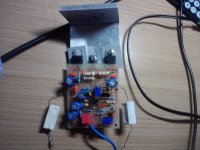
some time ago i tried to make my self familiar with this topology and i built something quite simple with spare parts i had aside and i was impressed by the sound quality despite the poor quality parts used.
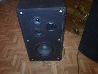
Sakis yes there has been a lot of time since we last talked. you have an amp schematic named G amp and a thread for it.have you build your amp and test it? Unfortunately i didnt manage to get a good set of speakers,just the one sony speaker i used to have for testing....
some time ago i tried to make my self familiar with this topology and i built something quite simple with spare parts i had aside and i was impressed by the sound quality despite the poor quality parts used.
Sakis yes there has been a lot of time since we last talked. you have an amp schematic named G amp and a thread for it.have you build your amp and test it? Unfortunately i didnt manage to get a good set of speakers,just the one sony speaker i used to have for testing....
Attachments
![P270112_01.21_[01].jpg](/community/data/attachments/335/335970-6b01dbf076e26d7ad82716f5ec7acd08.jpg)
If you want to build an old style amplifiers with a single transistor input stage, you should look at this one.
http://www.diyaudio.com/forums/solid-state/194453-very-simple-class-b-amplifier-3.html#post2671277
It uses MOSFETS in the output stage and uses a split power supply, which means that there is no decoupling capacitor on the output.
thanks for suggestion...i will have a look on this .
Another suggestion http://www.diyaudio.com/forums/solid-state/236256-retro-amp-50w-single-supply-11.html
Regards
Regards
The 2 circuits have nothing to do in terms of sound quality the one with the other .
As about the sound Panos is not quality of sound that got your attention more likely is the content of harmonics and the specific color and sonics produced from these circuits .
Kind regards
Sakis
As about the sound Panos is not quality of sound that got your attention more likely is the content of harmonics and the specific color and sonics produced from these circuits .
Kind regards
Sakis
yes but now im on a dilemma which schematic to choose, your G amp ,or the one that Apex audio suggested?
by the way what are the benefits of using regulated power supplies in such circuits?
what are the benefits of using modern type transistors such as 2SC5200 and not old type like 2n3773 in such circuits as output ?
so in these circuits the use of the typical Emmiter follower output stage or a Sziklai one ,wouldnt result in the desired content of harmonics and the specific color and sonics we want ,unlike quasi output stage i guess....
Well no... both circuits are pretty similar but also no the sonics of one amplifier come from the first stages and not the output scheme .
Fully regulated supply could be the best option for every class Ab amplifier provides better kick and better sound while rails are less modulated from audio signal and clip conditions
Using new transistors will bring some speed more but also decrease the safety margins
Kind regards
Sakis
Fully regulated supply could be the best option for every class Ab amplifier provides better kick and better sound while rails are less modulated from audio signal and clip conditions
Using new transistors will bring some speed more but also decrease the safety margins
Kind regards
Sakis
Hi maouna !
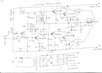
Here is the schematic of my modified Revox A78 power amp , it is old singleton , quasicompl. , bipolar supplied with virtual ground , work stable , it is not bad sounding SS amp for non critical music listening and everyday 24/7 use .
Best Regards !
Edit :
47K res. have to be connected direct to minus rail !!!
Attachments
Last edited:
Oooh, dat's bad! 'Probably more incentive for the OP to try it though, just to hear how weird an unstable amp sounds, as you suggest..... I had one of those years ago and inspite of my best efforts, i couldn't make it sound even just OK. The problem was instability, if the comp cap was large enough to prevent oscillation, it killed the high frequencies......Mike

Is there a prize for guessing which of the earlier Elektor audio designers came up with something that touchy. Was it really intended for music or some specialised audio application?
Last edited:
both are rated for Tjmax @ 150°C and both are rated @ 150W..........what are the benefits of using modern type transistors such as 2SC5200 and not old type like 2n3773 in such circuits as output ?...............
But the 3773 is much more robust and has far higher SOA.
The result is that the 5200 is far more likely to blow up if abused.
Why talk about these wintage transistors when newer and better sounding ones are available? Dear Maouna, if you are going to do anything near HiFi, dont even think about any of these. my sujjestion is Rod elliot's P3A which is a good sounding amp. Ask Sakis what trannies to be used.
If i am allowed to answer for Panos AKA maouna here ...
Panos is a young enthusiast and already been making some amplifiers if he is making also this one will be to evaluate the topology harmonics sonics and the differences between the topologies and circuits
under this its a very fine idea
Kind regards
Sakis
Panos is a young enthusiast and already been making some amplifiers if he is making also this one will be to evaluate the topology harmonics sonics and the differences between the topologies and circuits
under this its a very fine idea
Kind regards
Sakis
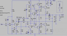
Made a layout based on one found here on the forum but added more space changed vbe multiplier, ad added a zobel network at the output. .component values and capacitor polarities are not specified yet on the layout....
Use BD911 instead 2SC5200 for 50W
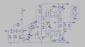
Made some changes of this amplifier made by APEX http://www.diyaudio.com/forums/solid-state/236256-retro-amp-50w-single-supply.html which i have already built and been very satisfied with.
The changes have to do with other parts used,a vbe multiplier added ,as well as a a more ''elegant'' feedback network employed as suggested.
waiting for your comments...
The changes have to do with other parts used,a vbe multiplier added ,as well as a a more ''elegant'' feedback network employed as suggested.
waiting for your comments...
Attachments
Last edited:
- Status
- This old topic is closed. If you want to reopen this topic, contact a moderator using the "Report Post" button.
- Home
- Amplifiers
- Solid State
- Retro amplifier 50 watt circuit