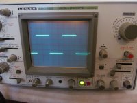
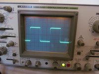
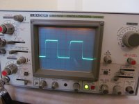
with no bias 1khz - 10khz - 20khz - 50khz - 100khz
nice
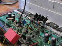
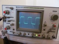
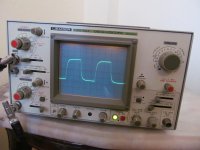
but there is bias 200mA through each output transistor - have you got bias or not?
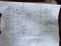
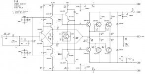
1. The bias circuit is not inherently safe (and probably has way too much adjustment range still). The pot should always go in the upper (C-B) leg.
2. You're using a cascoded VAS which may have high output impedance, but only an EF2 output stage. With compensation and stuff, it shouldn't be that bad, plus you have two pairs of outputs, but you may still be giving away some performance with lower-impedance loads (you should always be designing for 4 ohms, as even a number of "8 ohm" speakers' specs are blatantly lying).
2. You're using a cascoded VAS which may have high output impedance, but only an EF2 output stage. With compensation and stuff, it shouldn't be that bad, plus you have two pairs of outputs, but you may still be giving away some performance with lower-impedance loads (you should always be designing for 4 ohms, as even a number of "8 ohm" speakers' specs are blatantly lying).
nice
but there is bias 200mA through each output transistor - have you got bias or not?
Hi
I made some tests.Osc shows zero biased results.You can increase the bias up to 900ma.
No.1. The bias circuit is not inherently safe (and probably has way too much adjustment range still). The pot should always go in the upper (C-B) leg........
The schematic as drawn has the Vr in the correct location.
hi1. The bias circuit is not inherently safe (and probably has way too much adjustment range still). The pot should always go in the upper (C-B) leg.
2. You're using a cascoded VAS which may have high output impedance, but only an EF2 output stage. With compensation and stuff, it shouldn't be that bad, plus you have two pairs of outputs, but you may still be giving away some performance with lower-impedance loads (you should always be designing for 4 ohms, as even a number of "8 ohm" speakers' specs are blatantly lying).
I do not understand it which is low impedance stage ?
- Status
- This old topic is closed. If you want to reopen this topic, contact a moderator using the "Report Post" button.
- Home
- Amplifiers
- Solid State
- my last amplifier design "911"